|
|
|
PDF MC34064 Data sheet ( Hoja de datos )
| Número de pieza | MC34064 | |
| Descripción | (MC33064 / MC34064) UNDERVOLTAGE SENSING CIRCUIT | |
| Fabricantes | ON Semiconductor | |
| Logotipo | ||
Hay una vista previa y un enlace de descarga de MC34064 (archivo pdf) en la parte inferior de esta página. Total 12 Páginas | ||
|
No Preview Available !
MC34064, MC33064,
NCV33064
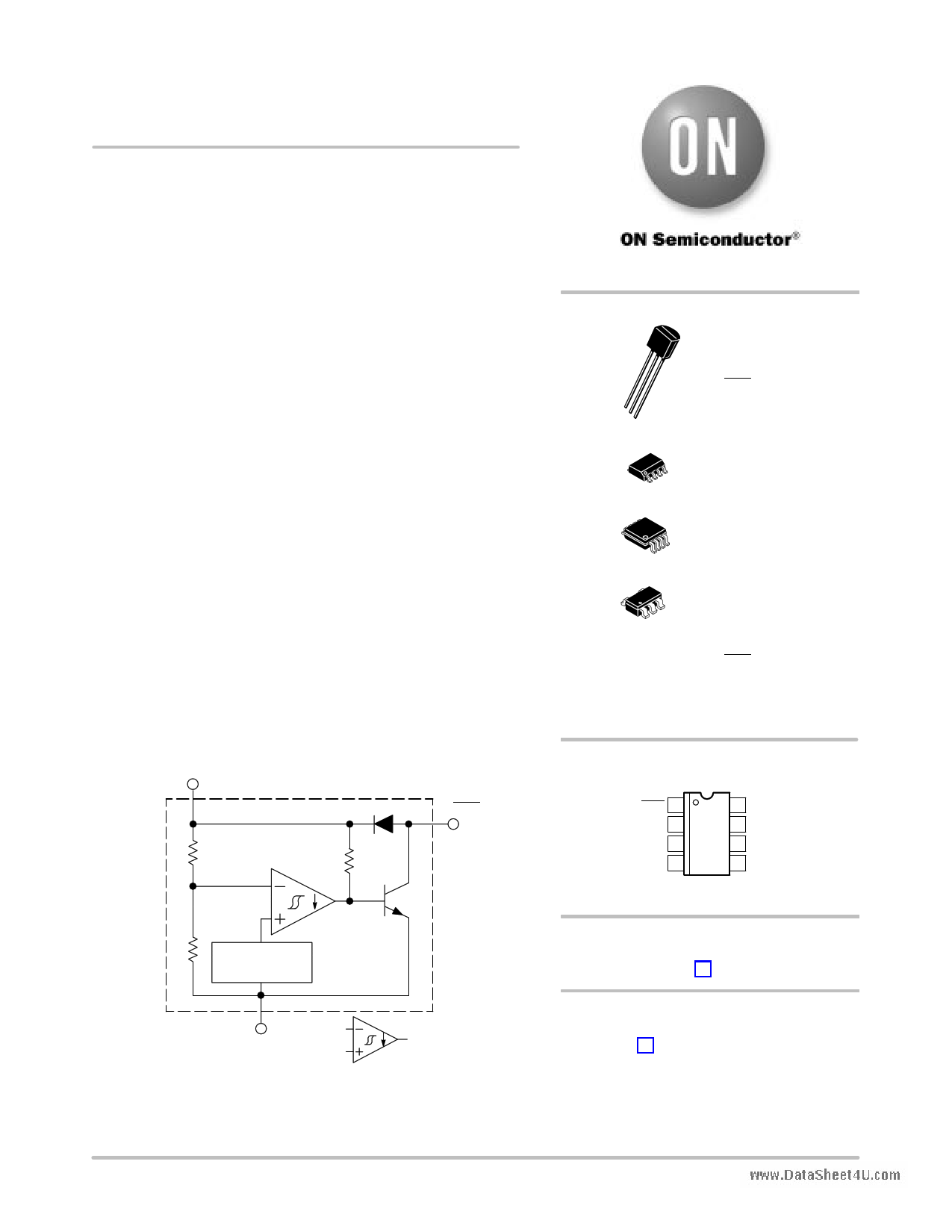
Undervoltage Sensing
Circuit
The MC34064 is an undervoltage sensing circuit specifically
designed for use as a reset controller in microprocessor−based
systems. It offers the designer an economical solution for low voltage
detection with a single external resistor. The MC34064 features a
trimmed−in−package bandgap reference, and a comparator with
precise thresholds and built-in hysteresis to prevent erratic reset
operation. The open collector reset output is capable of sinking in
excess of 10 mA, and operation is guaranteed down to 1.0 V input with
www.DataSheet4lUow.cosmtandby current. The MC devices are packaged in 3−pin TO-92,
micro size TSOP−5, 8−pin SOIC−8 and Micro8t surface mount
packages. The NCV device is packaged in SOIC−8 and TO−92.
Applications include direct monitoring of the 5.0 V MPU/logic
power supply used in appliance, automotive, consumer and industrial
equipment.
Features
• Trimmed−In−Package Temperature Compensated Reference
• Comparator Threshold of 4.6 V at 25°C
• Precise Comparator Thresholds Guaranteed Over Temperature
• Comparator Hysteresis Prevents Erratic Reset
• Reset Output Capable of Sinking in Excess of 10 mA
• Internal Clamp Diode for Discharging Delay Capacitor
• Guaranteed Reset Operation with 1.0 V Input
• Low Standby Current
• Economical TO−92, TSOP−5, SOIC−8 and Micro8 Surface Mount
Packages
• NCV Prefix for Automotive and Other Applications Requiring Site
and Control Changes
• Pb−Free Packages are Available
Input 2 (2)
Reset
1 (1)
1.2 Vref
GND 3 (4)
=
Sink Only
Positive True Logic
Pin numbers adjacent to terminals are for the 3−pin TO−92 package.
Pin numbers in parenthesis are for the 8−lead packages.
This device contains 21 active transistors.
Figure 1. Representative Block Diagram
© Semiconductor Components Industries, LLC, 2005
February, 2005 − Rev. 12
1
http://onsemi.com
1
2
3
8
1
8
1
5
1
TO−92
P SUFFIX
CASE 29
Pin 1. Reset
2. Input
3. Ground
SOIC−8
D SUFFIX
CASE 751
Micro8
DM SUFFIX
CASE 846A
TSOP−5
SN SUFFIX
CASE 483
Pin 1. Reset
2. Input
3. Ground
4. NC
5. NC
PIN CONNECTIONS
Reset 1
Input 2
N.C. 3
Ground 4
8 N.C.
7 N.C.
6 N.C.
5 N.C.
(Top View)
ORDERING INFORMATION
See detailed ordering and shipping information in the package
dimensions section on page 6 of this data sheet.
DEVICE MARKING INFORMATION
See general marking information in the device marking
section on page 7 of this data sheet.
Publication Order Number:
MC34064/D
1 page 
MC34064, MC33064, NCV33064
+
Power
Supply
−
2 (2)
−
+
1.2Vref
3 (4)
1.0k
1 (1)
+
− 2 (2)
−
+
1.2Vref
3 (4)
1 (1)
Solar
Cells
www.DataSheet4U.com
Vin = 11.5
to 14.5V
Figure 11. Voltage Monitor
Figure 12. Solar Powered Battery Charger
25mH
MPSW51A
VO = 5.0 V
+
470 +
IO = 50 mA
470 1N5819
22 680
+ 1.2k
4.7k
330
2 (2)
−
+
1.2Vref
1N756
1 (1)
Test
Line Regulation
Load Regulation
Output Ripple
Efficiency
Conditions
Vin = 11.5 V to 14.5 V, IO = 50 mA
Vin = 12.6 V, IO = 0 mA to 50 mA
Vin = 12.6 V, IO = 50 mA
Vin = 12.6 V, IO = 50 mA
Results
35 mV
12 mV
60 mVpp
77%
3 (4)
4.6V
Figure 13. Low Power Switching Regulator
VCC
RL
MTP3055EL
270
2 (2)
−
+
1.2Vref
1 (1)
3 (4)
Overheating of the logic level power MOSFET due to insufficient gate voltage can be prevented with the above
circuit. When the input signal is below the 4.6 V threshold of the MC34064, its output grounds the gate of the L2
MOSFET.
Figure 14. MOSFET Low Voltage Gate Drive Protection
http://onsemi.com
5
5 Page 
MC34064, MC33064, NCV33064
PACKAGE DIMENSIONS
DM SUFFIX
PLASTIC PACKAGE
CASE 846A−02
(Micro8)
ISSUE F
−A−
www.DataSheet4U.com
K
PIN 1 ID G
SEATING
−T− PLANE
0.038 (0.0015)
−B−
D 8 PL
0.08 (0.003) M T B S A S
C
H
J
L
NOTES:
1. DIMENSIONING AND TOLERANCING PER ANSI
Y14.5M, 1982.
2. CONTROLLING DIMENSION: MILLIMETER.
3. DIMENSION A DOES NOT INCLUDE MOLD FLASH,
PROTRUSIONS OR GATE BURRS. MOLD FLASH,
PROTRUSIONS OR GATE BURRS SHALL NOT
EXCEED 0.15 (0.006) PER SIDE.
4. DIMENSION B DOES NOT INCLUDE INTERLEAD
FLASH OR PROTRUSION. INTERLEAD FLASH OR
PROTRUSION SHALL NOT EXCEED 0.25 (0.010)
PER SIDE.
5. 846A−01 OBSOLETE, NEW STANDARD 846A−02.
MILLIMETERS
INCHES
DIM MIN MAX MIN MAX
A 2.90 3.10 0.114 0.122
B 2.90 3.10 0.114 0.122
C −−− 1.10 −−− 0.043
D 0.25 0.40 0.010 0.016
G 0.65 BSC
0.026 BSC
H 0.05 0.15 0.002 0.006
J 0.13 0.23 0.005 0.009
K 4.75 5.05 0.187 0.199
L 0.40 0.70 0.016 0.028
SOLDERING FOOTPRINT*
1.04
8X 0.041
0.38
0.015 8X
3.20
0.126
4.24 5.28
0.167 0.208
0.65
6X 0.0256
ǒ ǓSCALE 8:1
mm
inches
*For additional information on our Pb−Free strategy and soldering
details, please download the ON Semiconductor Soldering and
Mounting Techniques Reference Manual, SOLDERRM/D.
http://onsemi.com
11
11 Page | ||
| Páginas | Total 12 Páginas | |
| PDF Descargar | [ Datasheet MC34064.PDF ] | |
Hoja de datos destacado
| Número de pieza | Descripción | Fabricantes |
| MC3406 | N-Channel 30-V (D-S) MOSFET | FreesCale |
| MC34060A | (MC33060A / MC34060A) PRECISION SWITCHMODE PULSE WIDTH MODULATOR CONTROL CIRCUIT | Motorola Semiconductors |
| MC34060A | Voltage Mode Single Ended Controllers | ON Semiconductor |
| MC34062 | Pin-Programmable Overvoltage Sensing Circuit | Motorola Semiconductor |
| Número de pieza | Descripción | Fabricantes |
| SLA6805M | High Voltage 3 phase Motor Driver IC. |
Sanken |
| SDC1742 | 12- and 14-Bit Hybrid Synchro / Resolver-to-Digital Converters. |
Analog Devices |
|
DataSheet.es es una pagina web que funciona como un repositorio de manuales o hoja de datos de muchos de los productos más populares, |
| DataSheet.es | 2020 | Privacy Policy | Contacto | Buscar |