|
|
|
PDF DCMZ8H8SNA197 Data sheet ( Hoja de datos )
| Número de pieza | DCMZ8H8SNA197 | |
| Descripción | D Subminature | |
| Fabricantes | ITT Industries | |
| Logotipo | ||
Hay una vista previa y un enlace de descarga de DCMZ8H8SNA197 (archivo pdf) en la parte inferior de esta página. Total 30 Páginas | ||
|
No Preview Available !
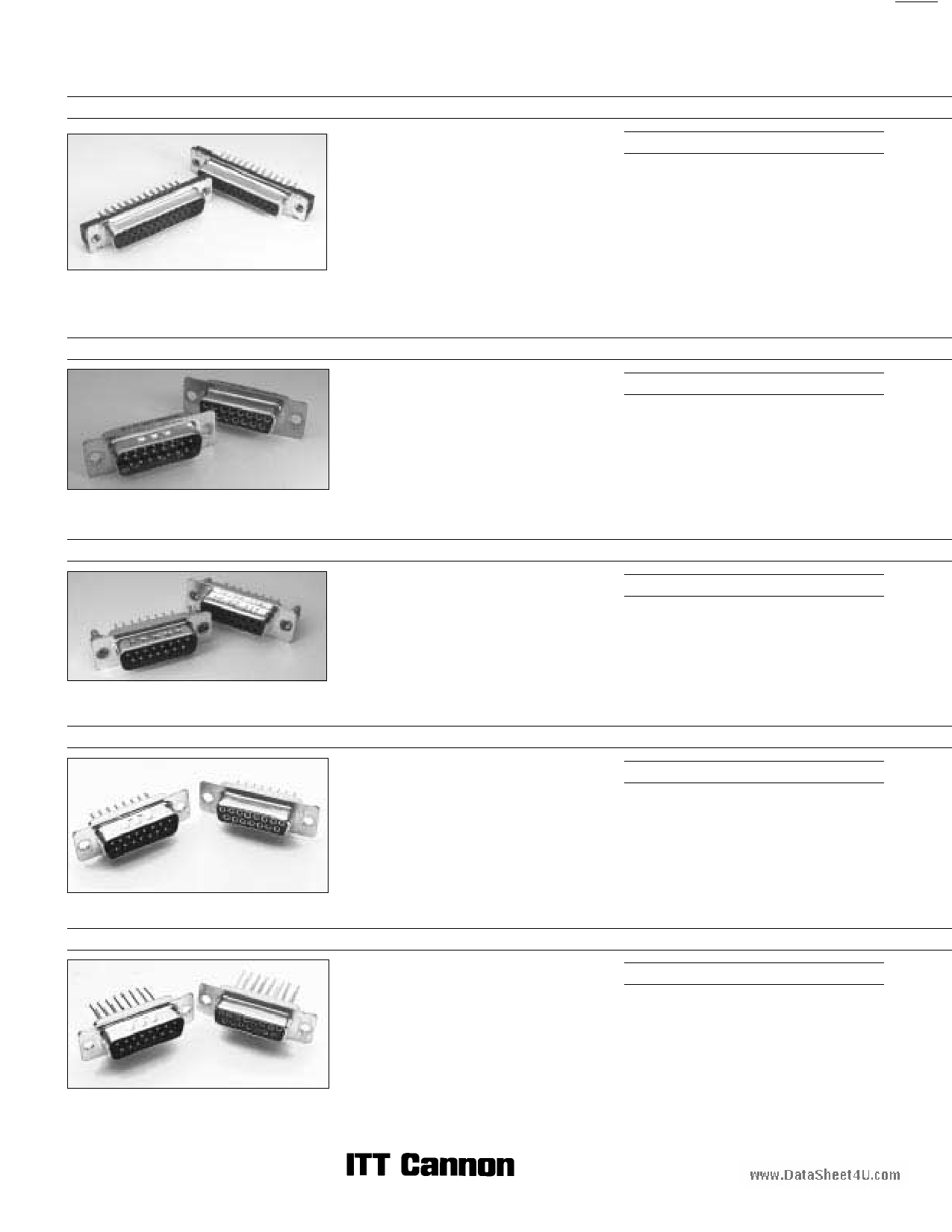
D Subminiature
Straight PCB Selection Guide
D*NG - Straight Pressfit Termination
See pages 4-5.
The D*NG is based upon the specification
CECC75-301-802. These connectors provide a
low-cost alternative to traditional through hole
solder contacts. Utilizing stamped ‘‘Eye of the
Needle’’ compliant contact tails per IEC-352-5, the
parts are quickly and easily mounted onto PCBs
without soldering, crimping or specialized tooling.
The socket contact engaging area utilizes a
‘‘spoon’’ shape with four points of
interconnection. Hardware options provide
flexibility and ensure that the final product fits the
electrical requirements of any application.
Product Features
ɀ Quick and easy press-in installation without
specialized tooling
ɀ ‘‘Spoon’’ socket contact provides improved
interface compared to ‘‘Tuning Fork’’
ɀ Closed-entry socket for secure blind mating
ɀ Front-shell only design based on
CECC 75-301-802
ɀ ‘‘Eye of the Needle’’ compliant contact tails
ɀ Press-in bolt for ground continuity
ɀ #4-40 UNC and M3 hardware options
D*M Straight Solder Termination (Machined) — Standard PC Tails
www.DataSheet4U.com
D*M straight PCB connectors, equivalent to
MIL-C-24308 qualified versions (except for
finishes) for printed circuit boards and backplanes
in demanding applications. Additional contact
lengths, hardware and finish options available;
consult factory for details.
See pages 6-7.
Product Features
ɀ 7.5 A current capacity
ɀ Machined contacts
ɀ 2 contact finishes
ɀ Optional vertical standoffs, screw locks, and
boardlocks (4 prongs)
ɀ UL file number E8572
ɀ Dimensionally compatible with Combo D
ZD* - Straight Solder Termination (Stamped)
ZD* straight connectors are available for
applications where price is the primary driver. They
are available with or without boardlocks and screw
locks.
Product Features
ɀ Stamped contacts with 5 A current capacity
ɀ Economical
ɀ Optional vertical standoffs with optional
harpoon style boardlocks or screw locks
See pages 8-9.
D* - Straight Solder Termination (Machined) — European PC Tails
See pages 10-11.
D* straight connectors are available for high
performance uses according to DIN 41652.
Available with European length OL contacts.
Select contact finish from 2 performance classes.
Product Features
ɀ High performance commercial connectors
ɀ Two contact finish performance classes
ɀ Optional vertical standoffs, threaded inserts
and pushfits/boardlocks
ɀ OL2 contact length, other lengths available
ɀ Tin plated contact PC tails (pin & socket)
ɀ Machined contacts
D* - Wrap Post Termination
D* straight connectors are available for high
performance uses according to DIN 41652.
Contacts available in two popular lengths.
Product Features
ɀ High performance commercial class
connectors
ɀ Two contact lengths for 2 or 3 wraps
ɀ Machined contacts
See pages 12-13.
Dimensions are shown in mm (inch)
2 Dimensions subject to change
1 page 
D Subminiature
90° PCB Selection Guide
D*M — 90° Solder Termination (Machined) — Standard Footprint .318ɍ or .283 inchɍɍ
See pages 16-17.
D*M 90° PCB connectors, equivalent to
MIL-C-24308 qualified versions (except for
finishes), for use with printed circuit boards in
demanding applications. Additional contact
lengths, hardware and finish options available;
consult factory for details.
Product Features
ɀ 7.5 A current capacity
ɀ Machined contacts
ɀ Two contact finishes
ɀ Metal bracket with threaded insert standard
ɀ Optional screw locks and boardlocks
ɀ UL file number E8572
ɀ Dimensionally compatible with Combo D
www.DataShZeEeDt4*U.—com90° Solder Termination (Stamped) — Standard Footprint .318 inchɍ
ZED* 90° connectors are available for applications
where price is the primary driver. They are
available with integrated plastic brackets with
Standard footprints.
Product Features
ɀ Stamped contacts with 5 A current capacity
ɀ Economical
ɀ Plastic bracket with integrated boardlocks and
grounding strap
ɀ Optional screw locks
See pages 18-19.
D* — 90° Solder Termination (Machined) — European Footprint 10,2ɍ or 9,4 mmɍɍ
See pages 20-27.
D* 90° connectors are available for high
performance uses according to DIN 41652.
Available with European footprint 1AON contacts,
plastic and metal brackets, #4-40 or M3 threads
and stamped pushfits/boardlocks. Contact finish
available in 2 performance classes.
Product Features
ɀ High performance commercial class
connectors
ɀ Two contact performance classes
ɀ Optional metal and plastic brackets, threaded
standoffs, clinch nuts, and stamped pushfits/
boardlocks
ɀ Tin plated contact PC tails (pin & socket)
ZD* — 90° Solder Termination (Stamped) — European Footprint 10,2 mmɍ
ZD* 90° connectors are available for applications
where price is the primary driver. They are
available with integrated plastic brackets with
European footprints.
Product Features
ɀ Stamped contacts with 5 A current capacity
ɀ Economical
ɀ Plastic bracket with integrated boardlocks and
grounding strap
ɀ Optional screw locks
See pages 28-29.
ɍ Connector footprint measured from the front shell.
ɍɍ Connector footprint measured from the rear shell.
Dimensions are shown in mm (inch)
14 Dimensions subject to change
5 Page 
D Subminiature
Combo D
Coaxial 90° — Standard Footprint .318ɍ or .283 inchɍɍ (Sizes DE-DC)
Receptacle
Reader’s Resource
ɀ For contact cavity arrangements,
see page 223.
www.DataShɀɀeeFFtoo4rrUPp.a.cCno.emlhcouletopuattst,ersnese,
see pages
page 221.
231-232.
ɀ For hardware views (Standard), see page 226.
ɀ For alternate bracket configuration (when
connectors are supplied without boardlocks),
see page 226.
ɀ For alternate 50 Ohm coaxial configuration,
see page 225.
75 Ohm Part Numbers* with Metal Bracket and Rivnut #4-40 UNC
Shell Size Layout
Part Number
Without Screw Locks
Without Boardlocks
Part Number
Without Screw Locks
With Boardlocks
Part Number
With Screw Locks
Without Boardlocks
DE 5W1 DEMP5C1SJA197 DEMC5C1SJA197 DEMD5C1SJA197
DA 7W2 DAMP7C2SJA197 DAMC7C2SJA197 DAMD7C2SJA197
DA 11W1
DAMP11C1SJA197
DAMC11C1SJA197
DAMD11C1SJA197
DA 3W3 DAMP3C3SJA197 DAMC3C3SJA197 DAMD3C3SJA197
DA 3WK3ឮ DAMP3CK3SJA197TM DAMC3CK3SJA197TM DAMD3CK3SJA197TM
DB 5W5 DBMP5C5SJA197 DBMC5C5SJA197 DBMD5C5SJA197
DB 9W4 DBMP9C4SJA197 DBMC9C4SJA197 DBMD9C4SJA197
DB 13W3 DBMP13C3SJA197 DBMC13C3SJA197 DBMD13C3SJA197
DB 17W2 DBMP17C2SJA197 DBMC17C2SJA197 DBMD17C2SJA197
DB 21W1 DBMP21C1SJA197 DBMC21C1SJA197 DBMD21C1SJA197
DC 8W8 DCMP8C8SJA197 DCMC8C8SJA197 DCMD8C8SJA197
DC 13W6
DCMP13C6SJA197
DCMC13C6SJA197
DCMD13C6SJA197
DC 17W5
DCMP17C5SJA197
DCMC17C5SJA197
DCMD17C5SJA197
DC 21WA4 DCMP21CA4SJA197 DCMC21CA4SJA197 DCMD21CA4SJA197
DC 25W3
DCMP25C3SJA197
DCMC25C3SJA197
DCMD25C3SJA197
DC 27W2
DCMP27C2SJA197
DCMC27C2SJA197
DCMD27C2SJA197
Notes: * For 50 Ohm Coaxial substitute X for C. Example: DEMP5X1SJA197
For contacts with 30 microinches gold substitute K126 for A197. Example: DEMP5C1SJK126
For DD Shell Sizes, see page 47.
ឮ Keyed.
Part Number
With Screw Locks
With Boardlocks
DEMG5C1SJA197
DAMG7C2SJA197
DAMG11C1SJA197
DAMG3C3SJA197
DAMG3CK3SJA197TM
DBMG5C5SJA197
DBMG9C4SJA197
DBMG13C3SJA197
DBMG17C2SJA197
DBMG21C1SJA197
DCMG8C8SJA197
DCMG13C6SJA197
DCMG17C5SJA197
DCMG21CA4SJA197
DCMG25C3SJA197
DCMG27C2SJA197
Engaging Face
A
C
B
E
BOARDLOCK
10°
Ø 0,76
(.030)
12,34
(.486) 8,64
(.340)
D
0,79
(.031)
2,92
(.115)
BRACKET,
METAL
RIVNUT
#4-40 UNC
0,56
(.023)
Ø 0,51
(.020)
2,54
(.100)
11,94 ± 0,33
(.470 ± .013)
3,89 (.153)
MIN
L
Screw lock, boardlock and signal contacts
removed for clarity
2,84
(.112)
4,33 ± 0,38
(.170 ± .015)
7,18 ± 0,25
(.283 ± .010)
F
W
6,50 ± 0,25
(.256 ± .010)
SCREW LOCK
#4-40 UNC
Note: ɋ Dimension varies with alternate bracket configuration, See Reader’s Resource page 226.
Dimensions
Shell Size
A
±0,38 (.015)
B
±0,13 (.005)
DE
30,81 (1.213)
16,33 (.643)
DA
39,14 (1.541)
24,66 (.971)
DB
53,04 (2.088)
38,38 (1.511)
DC
69,32 (2.729)
54,84 (2.159)
ɍ Connector footprint measured from the front shell.
ɍɍ Connector footprint measured from the rear shell.
C
±0,13 (.005)
24,99 (.984)
33,32 (1.312)
47.04 (1.852)
63,50 (2.500)
D
±0,13 (.005)
7,90 (.311)
7,90 (.311)
7,90 (.311)
7,90 (.311)
E
±0,38 (.015)
12,55 (.494)
12,55 (.494)
12,55 (.494)
12,55 (.494)
Screw lock, boardlock and coaxial contact
removed for clarity
F
±0,25 (.010)
10,90 (.429)
10,90 (.429)
10,90 (.429)
10,90 (.429)
W
±0,38 (.015)
6,94 (.273)
6,94 (.273)
6,94 (.273)
6,94 (.273)
L
±0,25 (.010)
0,76 (.030)
0,76 (.030)
0,76 (.030)
0,76 (.030)
Dimensions are shown in mm (inch)
Dimensions subject to change
45
11 Page | ||
| Páginas | Total 30 Páginas | |
| PDF Descargar | [ Datasheet DCMZ8H8SNA197.PDF ] | |
Hoja de datos destacado
| Número de pieza | Descripción | Fabricantes |
| DCMZ8H8SNA197 | D Subminature | ITT Industries |
| Número de pieza | Descripción | Fabricantes |
| SLA6805M | High Voltage 3 phase Motor Driver IC. |
Sanken |
| SDC1742 | 12- and 14-Bit Hybrid Synchro / Resolver-to-Digital Converters. |
Analog Devices |
|
DataSheet.es es una pagina web que funciona como un repositorio de manuales o hoja de datos de muchos de los productos más populares, |
| DataSheet.es | 2020 | Privacy Policy | Contacto | Buscar |