|
|
|
PDF IR3080PBF Data sheet ( Hoja de datos )
| Número de pieza | IR3080PBF | |
| Descripción | XPHASETM VRD10 CONTROL IC | |
| Fabricantes | International Rectifier | |
| Logotipo | ||
Hay una vista previa y un enlace de descarga de IR3080PBF (archivo pdf) en la parte inferior de esta página. Total 30 Páginas | ||
|
No Preview Available !
Data Sheet No. PD94705 revB
IR3080PbF
XPHASETM VRD10 CONTROL IC WITH VCCVID & OVERTEMP DETECT
DESCRIPTION
The IR3080 Control IC combined with an IR XPhaseTM Phase IC provides a full featured and flexible way to
implement a complete VRD 10 power solution. The “Control” IC provides overall system control and
interfaces with any number of “Phase ICs” which each drive and monitor a single phase of a multiphase
converter. The XPhaseTM architecture results in a power supply that is smaller, less expensive, and easier
to design while providing higher efficiency than conventional approaches.
The IR3080 is intended for desktop applications and includes the VCCVID and VRHOT functions required
for proper system operation.
FEATURES
www.DataSheet4U.com
• 6 bit VR10 compatible VID with 0.5% overall system accuracy
• 1 to X phases operation with matching phase ICs
• On-chip 700Ω VID Pull-up resistors with VID pull-up voltage input
• Programmable Dynamic VID Slew Rate
• No Discharge of output capacitors during Dynamic VID step-down (can be disabled)
• +/-300mV Differential Remote Sense
• Programmable 150kHz to 1MHz oscillator
• Programmable VID Offset and Load Line output impedance
• Programmable Softstart
• Programmable Hiccup Over-Current Protection with Delay to prevent false triggering
• Simplified Powergood provides indication of proper operation and avoids false triggering
• Operates from 12V input with 9.1V Under-Voltage Lockout
• 6.8V/5mA Bias Regulator provides System Reference Voltage
• 1.2V @ 150mA VCCVID Linear Regulator with Full Protection
• VCCVID Powergood with Programmable delay gates converter operation
• Programmable Converter Over-Temperature Detection and Output
• Small thermally enhanced 32L MLPQ package
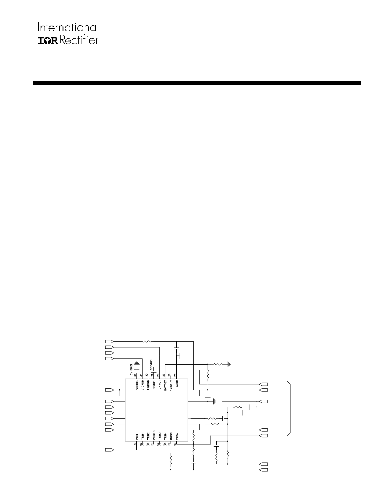
APPLICATION CIRCUIT
12V
VRHOT
POWERGOOD
VID POWERGOOD
RVCC
10 ohm
CVCC
0.1uF
RHOTSET2
Page 1
VCCVID
3.3V
VID5
VID0
VID1
VID2
VID3
VID4
RHOTSET1
1 VIDFB
2 VCCVID
3 VIDPWR
4 VID5
5 VID0
6 VID1
7 VID2
8 VID3
IR3080
CONTROL
IC
VCC
VBIAS
BBFB
EAOUT
FB
VDRP
IIN
OCSET
24
23
22
21
20
19
18
17
0.1uF
RCP
CCP
RDRP1 CDRP
RDRP
CCP1
ROSC
ROCSET
RVDAC
CVDAC
CFB
RFB1 RFB
RMPOUT
VBIAS
EA
5 Wire Analog Bus
to Phase ICs
ISHARE
VDAC
VOSENSE+
VOSENSE-
Remote
Sense
1 page 
IR3080PbF
PARAMETER
TEST CONDITION
MIN TYP MAX UNIT
VCC Under-Voltage Lockout
Start Threshold
8.6 9.1 9.6
V
Stop Threshold
8.4 8.9 9.4
V
Hysteresis
Start – Stop
150 200 300 mV
General
VCC Supply Current
8 11 14 mA
VIDPWR Supply Current
VID0-5 Open, I(VCCVID) = 0
400 550 1000 µA
VOSNS- Current
-0.3V ≤ VOSNS- ≤ 0.3V, All VID Codes -5.5 -4.5 -3.5 mA
VRHOT Comparator
HOTSET Bias Current
-2 -0.5 1
µA
Output Voltage
I(VRHOT) = 29mA
300 400 mV
VRHOT Leakage Current
Threshold Hysteresis
V(VRHOT) = 5.5V
TJ ≥ 85oC
0 10 µA
3 6 10 oC
Threshold Voltage
(increasing temperature)
TJ ≥ 85oC
MIN
4.73mV/ oC x TJ
+ 1.176V
TYP
4.73mV/ oC x TJ
+ 1.241V
MAX
4.73mV/ oC x TJ
+ 1.356V
V
Note 1: Guaranteed by design, but not tested in production
Note 2: VDAC Output is trimmed to compensate for Error Amplifier input offsets errors
Page 5
5 Page 
IR3080PbF
vL
iL L
RL
RCS
Current
Sense Amp
CSOUT
CCS
vCcS
VO
CO
Figure 5. Inductor Current Sensing and Current Sense Amplifier
The advantage of sensing the inductor current versus high side or low side sensing is that actual output current
being delivered to the load is obtained rather than peak or sampled information about the switch currents. The
output voltage can be positioned to meet a load line based on real time information. Except for a sense resistor in
series with the inductor, this is the only sense method that can support a single cycle transient response. Other
methods provide no information during either load increase (low side sensing) or load decrease (high side sensing).
An additional problem associated with peak or valley current mode control for voltage positioning is that they suffer
from peak-to-average errors. These errors will show in many ways but one example is the effect of frequency
variation. If the frequency of a particular unit is 10% low, the peak to peak inductor current will be 10% larger and
the output impedance of the converter will drop by about 10%. Variations in inductance, current sense amplifier
bandwidth, PWM prop delay, any added slope compensation, input voltage, and output voltage are all additional
sources of peak-to-average errors.
Current Sense Amplifier
A high speed differential current sense amplifier is located in the Phase IC, as shown in Figure 5. Its gain decreases
with increasing temperature and is nominally 34 at 25ºC and 29 at 125ºC (-1470 ppm/ºC). This reduction of gain
tends to compensate the 3850 ppm/ºC increase in inductor DCR. Since in most designs the Phase IC junction is
hotter than the inductors these two effects tend to cancel such that no additional temperature compensation of the
load line is required.
The current sense amplifier can accept positive differential input up to 100mV and negative up to -20mV before
clipping. The output of the current sense amplifier is summed with the DAC voltage and sent to the Control IC and
other Phases through an on-chip 10KΩ resistor connected to the ISHARE pin. The ISHARE pins of all the phases
are tied together and the voltage on the share bus represents the average current through all the inductors and is
used by the Control IC for voltage positioning and current limit protection.
Average Current Share Loop
Current sharing between phases of the converter is achieved by the average current share loop in each Phase IC.
The output of the current sense amplifier is compared with the share bus less a 20mV offset. If current in a phase is
smaller than the average current, the share adjust amplifier of the phase will activate a current source that reduces
the slope of its PWM ramp thereby increasing its duty cycle and output current. The crossover frequency of the
current share loop can be programmed with a capacitor at the SCOMP pin so that the share loop does not interact
with the output voltage loop.
Page 11
11 Page | ||
| Páginas | Total 30 Páginas | |
| PDF Descargar | [ Datasheet IR3080PBF.PDF ] | |
Hoja de datos destacado
| Número de pieza | Descripción | Fabricantes |
| IR3080PBF | XPHASETM VRD10 CONTROL IC | International Rectifier |
| Número de pieza | Descripción | Fabricantes |
| SLA6805M | High Voltage 3 phase Motor Driver IC. |
Sanken |
| SDC1742 | 12- and 14-Bit Hybrid Synchro / Resolver-to-Digital Converters. |
Analog Devices |
|
DataSheet.es es una pagina web que funciona como un repositorio de manuales o hoja de datos de muchos de los productos más populares, |
| DataSheet.es | 2020 | Privacy Policy | Contacto | Buscar |