|
|
|
PDF IRGBC30F Data sheet ( Hoja de datos )
| Número de pieza | IRGBC30F | |
| Descripción | INSULATED GATE BIPOLAR TRANSISTOR | |
| Fabricantes | International Rectifier | |
| Logotipo | ||
Hay una vista previa y un enlace de descarga de IRGBC30F (archivo pdf) en la parte inferior de esta página. Total 6 Páginas | ||
|
No Preview Available !
Previous Datasheet
Index
Next Data Sheet
www.DataSheet4U.com
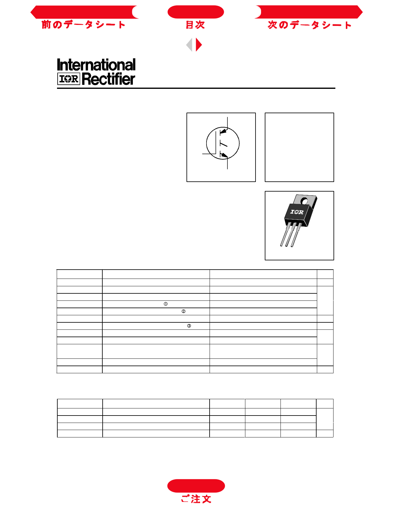
INSULATED GATE BIPOLAR TRANSISTOR
PD - 9.689A
IRGBC30F
Fast Speed IGBT
Features
• Switching-loss rating includes all "tail" losses
• Optimized for medium operating frequency ( 1 to
10kHz) See Fig. 1 for Current vs. Frequency curve
C
G
E
n-channel
Description
Insulated Gate Bipolar Transistors (IGBTs) from International Rectifier have
higher usable current densities than comparable bipolar transistors, while at
the same time having simpler gate-drive requirements of the familiar power
MOSFET. They provide substantial benefits to a host of high-voltage, high-
current applications.
VCES = 600V
VCE(sat) ≤ 2.1V
@VGE = 15V, IC = 17A
Absolute Maximum Ratings
VCES
IC @ TC = 25°C
IC @ TC = 100°C
ICM
ILM
VGE
EARV
PD @ TC = 25°C
PD @ TC = 100°C
TJ
TSTG
Parameter
Collector-to-Emitter Voltage
Continuous Collector Current
Continuous Collector Current
Pulsed Collector Current
Clamped Inductive Load Current
Gate-to-Emitter Voltage
Reverse Voltage Avalanche Energy
Maximum Power Dissipation
Maximum Power Dissipation
Operating Junction and
Storage Temperature Range
Soldering Temperature, for 10 sec.
Mounting torque, 6-32 or M3 screw.
TO-220AB
Max.
600
31
17
120
120
±20
10
100
42
-55 to +150
300 (0.063 in. (1.6mm) from case)
10 lbf•in (1.1N•m)
Units
V
A
V
mJ
W
°C
Thermal Resistance
RθJC
RθCS
RθJA
Wt
Parameter
Junction-to-Case
Case-to-Sink, flat, greased surface
Junction-to-Ambient, typical socket mount
Weight
C-57
Min.
—
—
—
—
Typ.
—
0.50
—
2.0 (0.07)
Max.
1.2
—
80
—
Units
°C/W
g (oz)
To Order
1 page 
Previous Datasheet
Index
Next Data Sheet
IRGBC30F
1400
V GE = 0V,
f = 1MHz
Cies = Cge + C gc , Cce SHORTED
1200 Cres = C gc
Coes = Cce + C gc
1000
Cies
800
Coes
600
400
Cres
200
0
1 10 100
V C E , C ollector-to-E m itter V oltage (V )
Fig. 7 - Typical Capacitance vs.
Collector-to-Emitter Voltage
20
VCE = 400V
IC = 17A
16
12
8
4
0
0 5 10 15 20 25
Q g , Total Gate Charge (nC)
Fig. 8 - Typical Gate Charge vs.
Gate-to-Emitter Voltage
30
2.7
VCC = 480V
VG E = 15V
TC = 25°C
2.6 IC = 17A
2.5
2.4
2.3
2.2
0
10 20 30 40 50 60
R G , Gate Resistance (Ω )
W
Fig. 9 - Typical Switching Losses vs. Gate
Resistance
10
IC = 34A
I C = 17A
IC = 8.5A
RG = 23 Ω
V GE = 15 V
1 VCC = 480V
-60 -40 -20 0 20 40 60 80 100 120 140 160
TC, C ase Tem perature (°C )
Fig. 10 - Typical Switching Losses vs.
Case Temperature
C-61
To Order
5 Page | ||
| Páginas | Total 6 Páginas | |
| PDF Descargar | [ Datasheet IRGBC30F.PDF ] | |
Hoja de datos destacado
| Número de pieza | Descripción | Fabricantes |
| IRGBC30F | INSULATED GATE BIPOLAR TRANSISTOR | International Rectifier |
| IRGBC30FD2 | INSULATED GATE BIPOLAR TRANSISTOR | International Rectifier |
| IRGBC30K | INSULATED GATE BIPOLAR TRANSISTOR | International Rectifier |
| IRGBC30K-S | INSULATED GATE BIPOLAR TRANSISTOR | International Rectifier |
| Número de pieza | Descripción | Fabricantes |
| SLA6805M | High Voltage 3 phase Motor Driver IC. |
Sanken |
| SDC1742 | 12- and 14-Bit Hybrid Synchro / Resolver-to-Digital Converters. |
Analog Devices |
|
DataSheet.es es una pagina web que funciona como un repositorio de manuales o hoja de datos de muchos de los productos más populares, |
| DataSheet.es | 2020 | Privacy Policy | Contacto | Buscar |