|
|
|
PDF SCAN182245A Data sheet ( Hoja de datos )
| Número de pieza | SCAN182245A | |
| Descripción | Non-Inverting Transceiver | |
| Fabricantes | Fairchild Semiconductor | |
| Logotipo | ||
Hay una vista previa y un enlace de descarga de SCAN182245A (archivo pdf) en la parte inferior de esta página. Total 13 Páginas | ||
|
No Preview Available !
December 1993
Revised January 2001
SCAN182245A
Non-Inverting Transceiver
with 25Ω Series Resistor Outputs
General Description
The SCAN182245A is a high performance BiCMOS bidi-
rectional line driver featuring separate data inputs orga-
nized into dual 9-bit bytes with byte-oriented output enable
and direction control signals. This device is compliant with
IEEE 1149.1 Standard Test Access Port and Boundary
Scan Architecture with the incorporation of the defined
boundary-scan test logic and test access port consisting of
Test Data Input (TDI), Test Data Out (TDO), Test Mode
Select (TMS), and Test Clock (TCK).
Features
s High performance BiCMOS technology
s 25Ω series resistors in outputs eliminate the need for
external terminating resistors
s Dual output enable control signals
s 3-STATE outputs for bus-oriented applications
s 25 mil pitch SSOP (Shrink Small Outline Package)
s IEEE 1149.1 (JTAG) Compliant
s Includes CLAMP, IDCODE and HIGHZ instructions
s Additional instructions SAMPLE-IN, SAMPLE-OUT and
EXTEST-OUT
s Power Up 3-STATE for hot insert
s Member of Fairchild’s SCAN Products
Ordering Code:
Order Number
Package
Number
Package Description
SCAN182245ASSC
MS56A
56-Lead Shrink Small Outline Package (SSOP), JEDEC MO-118, 0.300 Wide
SCAN182245AMTD
MTD56
56-Lead Thin Shrink Small Outline Package (TSSOP), JEDEC MO-153, 6.1mm Wide
Devices also available in Tape and Reel. Specify by appending the suffix letter “X” to the ordering code.
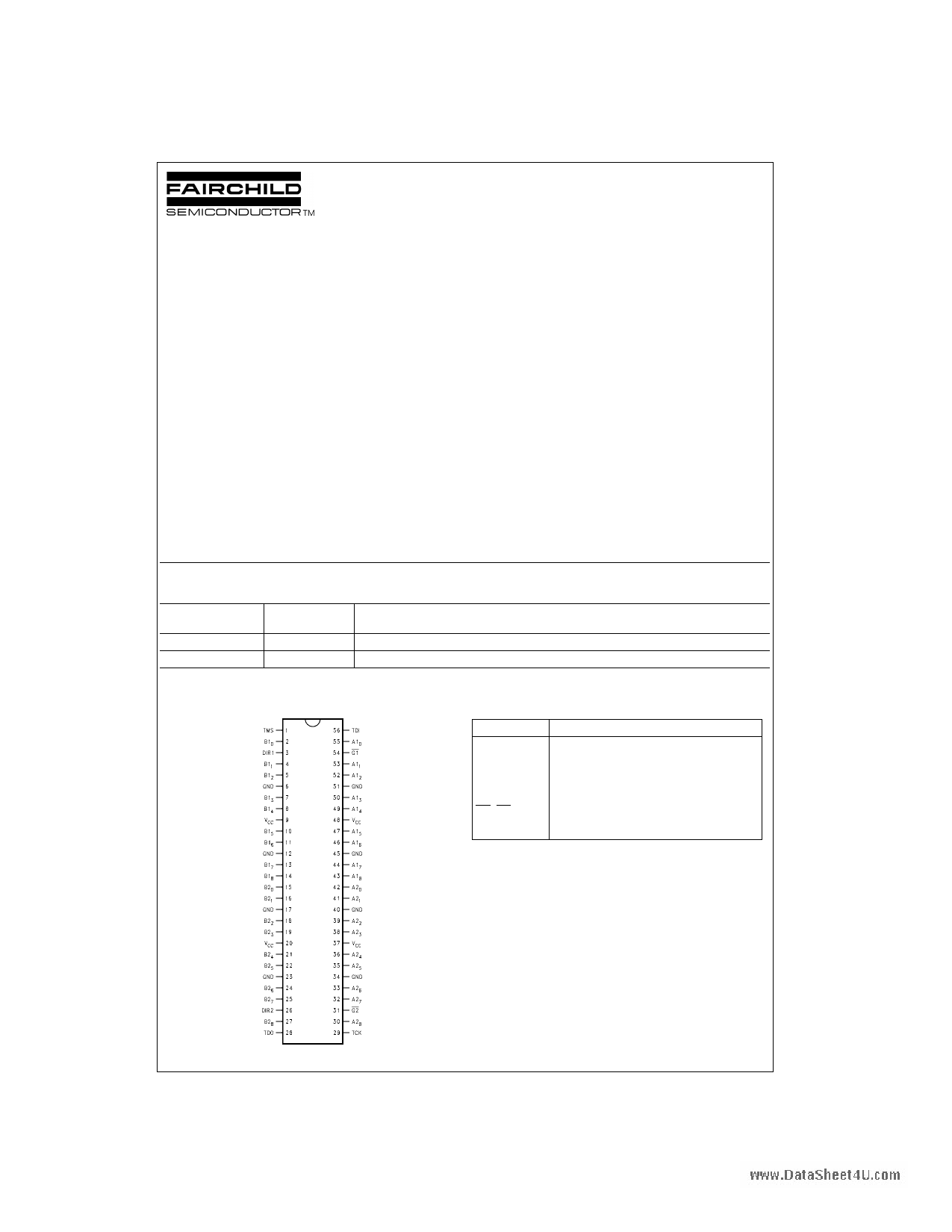
Connection Diagram
Pin Descriptions
Pin Names
A1(0–8)
B1(0–8)
A2(0–8)
B2(0–8)
G1, G2
DIR1, DIR2
Description
Side A1 Inputs or 3-STATE Outputs
Side B1 Inputs or 3-STATE Outputs
Side A2 Inputs or 3-STATE Outputs
Side B2 Inputs or 3-STATE Outputs
Output Enable Pins (Active LOW)
Direction of Data Flow Pins
© 2001 Fairchild Semiconductor Corporation DS011657
www.fairchildsemi.com
1 page 
Description of BOUNDARY-SCAN Circuitry (Continued)
Input BOUNDARY-SCAN Register
Scan Chain Definition (40 Bits in Length)
When Sample In is Active
5 www.fairchildsemi.com
5 Page 
AC Operating Requirements
Scan Test Operation
VCC TA = −40°C to +85°C
Symbol
Parameter
(V) CL = 50 pF
(Note 7)
Guaranteed Minimum
tS Setup Time
Data to TCK (Note 8)
5.0 4.8
tH Hold Time
Data to TCK (Note 8)
5.0 2.5
tS Setup Time, H or L
G1, G2 to TCK (Note 9)
5.0 4.1
tH Hold Time, H or L
TCK to G1, G2 (Note 9)
5.0 1.7
tS Setup Time, H or L
DIR1, DIR2 to TCK (Note 10)
5.0 4.2
tH Hold Time, H or L
TCK to DIR1, DIR2 (Note 10)
5.0 2.3
tS Setup Time
Internal OE to TCK (Note 11)
5.0 3.8
tH Hold Time, H or L
TCK to Internal OE (Note 10)
5.0 2.3
tS Setup Time, H or L
TMS to TCK
5.0 8.7
tH Hold Time, H or L
TCK to TMS
5.0 1.5
tS Setup Time, H or L
TDI to TCK
5.0 6.7
tH Hold Time, H or L
TCK to TDI
5.0 5.0
tW Pulse Width TCK:
H
5.0
L
10.2
8.5
fMAX
Maximum TCK
Clock Frequency
5.0 50
tPU Wait Time,
Power Up to TCK
5.0 100
tDN Power Down Delay
Note 7: Voltage Range 5.0V ± 0.5V
0.0 100
Note 8: Timing pertains to the TYPE1 BSR and TYPE2 BSR after the buffer (BSR 0–8, 9–17, 18–26, 27–35, 36–44, 45–53, 54–62, 63–71).
Note 9: Timing pertains to BSR 74 and 78 only.
Note 10: Timing pertains to BSR 75 and 79 only.
Note 11: Timing pertains to BSR 72, 73, 76 and 77 only.
Note: All Input Timing Delays involving TCK are measured from the rising edge of TCK.
Units
ns
ns
ns
ns
ns
ns
ns
ns
ns
ns
ns
ns
ns
MHz
ns
ms
Capacitance
Symbol
Parameter
Typ
CIN Input Capacitance
5.9
CI/O (Note 12) Output Capacitance
13.7
Note 12: CI/O is measured at frequency f = 1 MHz, per MIL-STD-883B, Method 3012.
Units
pF
pF
Conditions, TA = 25°C
VCC = 0.0V (Gn, DIRn)
VCC = 5.0V (An, Bn)
11 www.fairchildsemi.com
11 Page | ||
| Páginas | Total 13 Páginas | |
| PDF Descargar | [ Datasheet SCAN182245A.PDF ] | |
Hoja de datos destacado
| Número de pieza | Descripción | Fabricantes |
| SCAN182245A | Non-Inverting Transceiver | Fairchild Semiconductor |
| SCAN182245A | Non-Inverting Transceiver | National Semiconductor |
| Número de pieza | Descripción | Fabricantes |
| SLA6805M | High Voltage 3 phase Motor Driver IC. |
Sanken |
| SDC1742 | 12- and 14-Bit Hybrid Synchro / Resolver-to-Digital Converters. |
Analog Devices |
|
DataSheet.es es una pagina web que funciona como un repositorio de manuales o hoja de datos de muchos de los productos más populares, |
| DataSheet.es | 2020 | Privacy Policy | Contacto | Buscar |