|
|
|
PDF 29152BU Data sheet ( Hoja de datos )
| Número de pieza | 29152BU | |
| Descripción | MIC29152BU | |
| Fabricantes | Micrel Semiconductor | |
| Logotipo | ||
Hay una vista previa y un enlace de descarga de 29152BU (archivo pdf) en la parte inferior de esta página. Total 20 Páginas | ||
|
No Preview Available !
MIC29150/29300/29500/29750
Micrel
MIC29150/29300/29500/29750 Series
High-Current Low-Dropout Regulators
General Description
Features
The MIC29150/29300/29500/29750 are high current, high • High Current Capability
accuracy, low-dropout voltage regulators. Using Micrel's
MIC29150/29151/29152/29153 ................................ 1.5A
proprietary Super ßeta PNP™ process with a PNP pass
MIC29300/29301/29302/29303 ................................... 3A
element, these regulators feature 300mV to 370mV (full load)
MIC29500/29501/29502/29503 ................................... 5A
dropout voltages and very low ground current. Designed for
MIC29750/29751/29752 ........................................... 7.5A
high current loads, these devices also find applications in • Low-Dropout Voltage ....................... 350mV at Full Load
lower current, extremely low dropout-critical systems, where • Low Ground Current
their tiny dropout voltage and ground current values are • Accurate 1% Guaranteed Tolerance
important attributes.
• Extremely Fast Transient Response
The MIC29150/29300/29500/29750 are fully protected against
overcurrent faults, reversed input polarity, reversed lead
insertion, overtemperature operation, and positive and nega-
tive transient voltage spikes. Five pin fixed voltage versions
feature logic level ON/OFF control and an error flag which
signals whenever the output falls out of regulation. Flagged
states include low input voltage (dropout), output current
• Reverse-battery and “Load Dump” Protection
• Zero-Current Shutdown Mode (5-Pin versions)
• Error Flag Signals Output Out-of-Regulation
(5-Pin versions)
• Also Characterized For Smaller Loads With Industry-
Leading Performance Specifications
• Fixed Voltage and Adjustable Versions
limit, overtemperature shutdown, and extremely high voltage Applications
spikes on the input.
• Battery Powered Equipment
On the MIC29xx1 and MIC29xx2, the ENABLE pin may be • High-Efficiency “Green” Computer Systems
tied to VIN if it is not required for ON/OFF control. The • Automotive Electronics
ManICd 2s9u1rf5a0c/e29m3o0u0n/2t 9T5O0-026a3repaavcakilaagbeles.inT3h-eanMdIC5-2p9in75T0wOww7-.2D.a52taA0Sheet4U.co••m
High-Efficiency
High-Efficiency
Linear Power Supplies
Post-Regulator For Switching
Supply
regulators are available in 3- and 5-pin TO-247 packages.
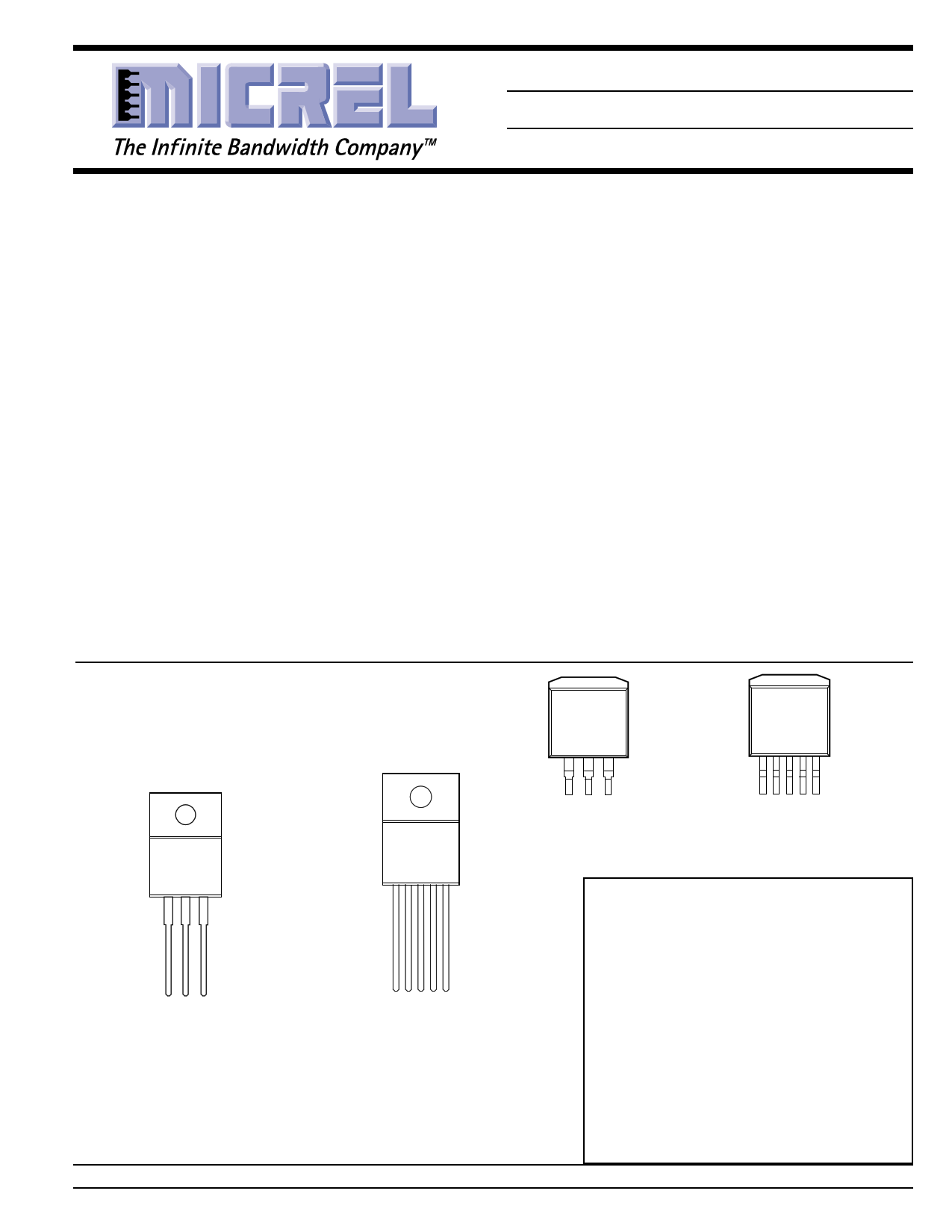
Pin Configuration
123
MIC29150/29300/
29500BT and
MIC29750BWT
123
MIC29150/29300BU
1 23 4 5
MIC29151/29152/29153BU
MIC29301/29302/29303BU
MIC29501/29502/29503BU
Pinout On all devices, the Tab is grounded.
MIC29150/29300/29500/29750 Three Terminal
Devices:
Pin 1 = Input, 2 = Ground, 3 = Output
1 23 45
MIC29151/29152/29153BT
MIC29301/29302/29303BT
MIC29501/29502/29503BT
MIC29751/29752BWT
MIC29151/29301/29501/29751 Five Terminal
Fixed Voltage Devices:
Pin 1 = Enable, 2 = Input, 3 = Ground, 4 = Output,
5 = Flag
MIC29152/29302/29502/29752 Adjustable with
ON/OFF Control
Pin 1 = Enable, 2 = Input, 3 = Ground, 4 = Output,
5 = Adjust
MIC29153/29303/29503 Adjustable with Flag
Pin 1 = Flag, 2 = Input, 3 = Ground, 4 = Output,
5 = Adjust
Micrel, Inc. • 1849 Fortune Drive • San Jose, CA 95131 • USA • tel + 1 (408) 944-0800 • fax + 1 (408) 944-0970 • http://www.micrel.com
March 2000
1 MIC29150/29300/29500/29750
1 page 
MIC29150/29300/29500/29750
Micrel
Notes
Note 1: Maximum positive supply voltage of 60V must be of limited duration (<100msec) and duty cycle (≤1%). The maximum continuous supply
voltage is 26V.
Note 2:
Note 3:
Note 4:
Full Load current (IFL) is defined as 1.5A for the MIC29150, 3A for the MIC29300, 5A for the MIC29500, and 7.5A for the MIC29750 families.
Dropout voltage is defined as the input-to-output differential when the output voltage drops to 99% of its nominal value with VOUT + 1V applied
to VIN
VIN = VOUT (nominal) + 1V. For example, use VIN = 4.3V for a 3.3V regulator or use 6V for a 5V regulator. Employ pulse-testing procedures to
minimize temperature rise.
Note 5: Ground pin current is the regulator quiescent current. The total current drawn from the source is the sum of the load current plus the ground
pin current.
Note 6: Output voltage temperature coefficient is defined as the worst case voltage change divided by the total temperature range.
Note 7:
Note 8:
Note 9:
Thermal regulation is defined as the change in output voltage at a time T after a change in power dissipation is applied, excluding load or line
regulation effects. Specifications are for a 200mA load pulse at VIN = 20V (a 4W pulse) for T = 10ms.
VREF ≤ VOUT ≤ (VIN – 1 V), 2.3V ≤ VIN ≤ 26V, 10mA < IL ≤ IFL, TJ ≤ TJ MAX.
Comparator thresholds are expressed in terms of a voltage differential at the Adjust terminal below the nominal reference voltage measured at
6V input. To express these thresholds in terms of output voltage change, multiply by the error amplifier gain = VOUT /VREF = (R1 + R2)/R2. For
example, at a programmed output voltage of 5V, the Error output is guaranteed to go low when the output drops by 95 mV x 5V/1.240 V = 384
mV. Thresholds remain constant as a percent of VOUT as VOUT is varied, with the dropout warning occurring at typically 5% below nominal,
7.7% guaranteed.
Note 10: VEN ≤ 0.8V and VIN ≤ 26V, VOUT = 0.
Note 11: When used in dual supply systems where the regulator load is returned to a negative supply, the output voltage must be diode clamped to
ground.
Block Diagram
IN
FLAG
1.180V Reference 1.240V
O.V.
ILIMIT
28V
OUT
R1*
EN
Typical Applications
Thermal
Shut-
down
* Feedback network in fixed versions only
† Adjustable version only
ADJ†
R2*
GND
5V ± 5%
MIC29500-3.3
3.3V ± 1% @ 5A
47µF
VIN
R1
VOUT
R2
Figure 1. Fixed output voltage.
March 2000
VOUT = 1.240V × [1 + (R1 / R2)]
Figure 2. Adjustable output voltage configuration. For
best results, the total series resistance should be small
enough to pass the minimum regulator load current.
5 MIC29150/29300/29500/29750
5 Page 
MIC29150/29300/29500/29750
MIC29501-xx/2 Enable Current
vs. Temperaure
30
25
20
VEN = 5V
15
10 VEN = 2V
5
0
-60 -30 0 30 60 90 120 150
TEMPERATURE (°C)
MIC29502/3 Adjust Pin Current
vs. Temperature
80
70
60
50
40
30
20 ILOAD = 10mA
10
0
-60 -30 0 30 60 90 120 150
TEMPERATURE (°C)
1500
1000
500
0
-5006
5
4
3
2
1
0
-1
-5
MIC2950x
Load Transient
COUT = 10 µF
ILOAD = 10mA
0 5 10 15 20 25
TIME (ms)
100
50
0
-50
-180.02
6.2
MIC2950x
Line Transient
COUT = 10 µF
ILOAD = 10mA
4.2
2.2
-0.2 0.0 0.2 0.4 0.6 0.8 1.0 1.2 1.4
TIME (ms)
MIC2950x Output Impedance
vs. Frequency
10
1
0.1
0.01
0.001
FREQUENCY (Hz)
Micrel
100
50
0
-50
-1006
5
4
3
2
1
0
-1
-5
MIC2950x
Load Transient
COUT = 100 µF
ILOAD = 10mA
0 5 10 15 20 25
TIME (ms)
MIC2950x
Line Transient
20
10 COUT = 100 µF
0
-10
-82.20
6.2 ILOAD = 10mA
4.2
2.2
-0.2 0.0 0.2 0.4 0.6 0.8 1.0 1.2 1.4
TIME (ms)
March 2000
11 MIC29150/29300/29500/29750
11 Page | ||
| Páginas | Total 20 Páginas | |
| PDF Descargar | [ Datasheet 29152BU.PDF ] | |
Hoja de datos destacado
| Número de pieza | Descripción | Fabricantes |
| 29152BU | MIC29152BU | Micrel Semiconductor |
| Número de pieza | Descripción | Fabricantes |
| SLA6805M | High Voltage 3 phase Motor Driver IC. |
Sanken |
| SDC1742 | 12- and 14-Bit Hybrid Synchro / Resolver-to-Digital Converters. |
Analog Devices |
|
DataSheet.es es una pagina web que funciona como un repositorio de manuales o hoja de datos de muchos de los productos más populares, |
| DataSheet.es | 2020 | Privacy Policy | Contacto | Buscar |