|
|
|
PDF NCP5006 Data sheet ( Hoja de datos )
| Número de pieza | NCP5006 | |
| Descripción | Compact Backlight LED Boost Driver | |
| Fabricantes | ON Semiconductor | |
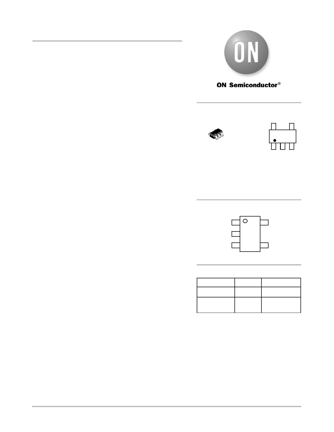
| Logotipo | ||
Hay una vista previa y un enlace de descarga de NCP5006 (archivo pdf) en la parte inferior de esta página. Total 24 Páginas | ||
|
No Preview Available !
NCP5006
Compact Backlight LED
Boost Driver
The NCP5006 is a high efficiency boost converter operating in
current loop, based on a PFM mode, to drive White LED. The current
mode regulation allows a uniform brightness of the LEDs. The chip
has been optimized for small ceramic capacitors, capable to supply
up to 1.0 W output power.
Features
• 2.7 to 5.5 V Input Voltage Range
• Vout to 24 V Output Compliance Allows up to 5 LEDs Drive in
Series
• Built−in Overvoltage Protection
• Inductor Based Converter brings up to 90% Efficiency
• Constant Output Current Regulation
• 0.3 mA Standby Quiescent Current
• Includes Dimming Function (PWM)
• Enable Function Driven Directly from Low Battery Voltage Source
• Automatic LEDs Current Matching
• Thermal Shutdown Protection
• All Pins are Fully ESD Protected
• Low EMI Radiation
www.DataSheet4U.com
• Pb−Free Package is Available
Typical Applications
• LED Display Back Light Control
• Keyboard Back Light
• High Efficiency Step Up Converter
http://onsemi.com
5
1
TSOP−5
SN SUFFIX
CASE 483
MARKING
DIAGRAM
5
DCSAYWG
G
1
DCS = Device Code
A = Assembly Location
Y = Year
W = Work Week
G = Pb−Free Package
(Note: Microdot may be in either location)
PIN CONNECTIONS
Vout 1
GND 2
5 Vbat
FB 3
4 EN
(Top View)
ORDERING INFORMATION
Device
Package
Shipping†
NCP5006SNT1
TSOP−5 3000 Tape & Reel
NCP5006SNT1G TSOP−5 3000 Tape & Reel
(Pb−Free)
†For information on tape and reel specifications,
including part orientation and tape sizes, please
refer to our Tape and Reel Packaging Specifications
Brochure, BRD8011/D.
© Semiconductor Components Industries, LLC, 2006
March, 2006 − Rev. 2
1
Publication Order Number:
NCP5006/D
1 page 
NCP5006
ANALOG SECTION (Typical values are referenced to TA = +25°C, Min & Max values are referenced −25°C to +85°C ambient
temperature, unless otherwise noted.)
Rating
Pin Symbol Min Typ Max
High Level Input Voltage
Low Level Input Voltage
4 EN 1.3 − −
− − 0.4
EN Pull Down Resistor
Feedback Voltage Threshold
4 REN − 100 −
3 FB 185 200 225
Output Current Stabilization Time Delay following a DC/DC Start−up,
@ Vbat = 3.60 V, L = 22 mH, Iout = 20 mA
Internal Switch ON Resistor @ Tamb = +25°C
5. The overall tolerance depends upon the accuracy of the external resistor.
1
1
Ioutdly
QRDSON
− 100 −
− 1.7 −
Unit
V
V
kW
mV
ms
W
ESD PROTECTION
The NCP5006 includes silicon devices to protect the pins
against the ESD spikes voltages. To cope with the different
ESD voltages developed in the applications, the built−in
structures have been designed to handle "2.0 kVin Human
Body Model (HBM) and "200 V in Machine Model (MM)
on each pin.
DC/DC OPERATION
The DC/DC converter is designed to supply a constant
current to the external load, the circuit being powered from
a standard battery supply. Since the regulation is made by
means of a current loop, the output voltage will varies
depending upon the dynamic impedance presented by the
load.
Considering high intensity LED, the output voltage can
range from a low 6.40 V (two LED in series biased with a
low current), up to 21 V, the voltage compliance the chip
can sustain continuously.
The basic DC/DC structure is depicted in Figure 3. With
a 28 V maximum rating voltage capability, the power
device can accommodate high voltage source without any
leakage current downgrading.
Vbat
POR
Vdsense
L1
22 mH
1
D1
Q1 Vds
LOGIC
CONTROL
TIME_OUT
ZERO_CROSSING
RESET
Vdsense
+
V(Ipeak)
−
−
+
GND
R1
C2
Vref
GND
Figure 3. Basic DC/DC Converter Structure
GND
3
R2
xR Vs
GND
http://onsemi.com
5
5 Page 
NCP5006
TYPICAL OPERATING WAVEFORMS
Vout
Inductor
Current
Conditions: Vbat = 3.6 V, Lout = 22 mH, 5 LED, Iout = 15 mA
Figure 20. Typical Power Up Response
Vout
Inductor
Current
Conditions: Vbat = 3.6 V, Lout = 22 mH, 5 LED, Iout = 15 mA
Figure 21. Typical Start−Up Inductor Current and Output Voltage
http://onsemi.com
11
11 Page | ||
| Páginas | Total 24 Páginas | |
| PDF Descargar | [ Datasheet NCP5006.PDF ] | |
Hoja de datos destacado
| Número de pieza | Descripción | Fabricantes |
| NCP500 | 150 mA CMOS Low Noise Low-Dropout Voltage Regulator | ON |
| NCP5005 | Compact Backlight LED Boost Driver | ON Semiconductor |
| NCP5006 | Compact Backlight LED Boost Driver | ON Semiconductor |
| NCP5007 | Compact Backlight LED Boost Driver | ON |
| Número de pieza | Descripción | Fabricantes |
| SLA6805M | High Voltage 3 phase Motor Driver IC. |
Sanken |
| SDC1742 | 12- and 14-Bit Hybrid Synchro / Resolver-to-Digital Converters. |
Analog Devices |
|
DataSheet.es es una pagina web que funciona como un repositorio de manuales o hoja de datos de muchos de los productos más populares, |
| DataSheet.es | 2020 | Privacy Policy | Contacto | Buscar |