|
|
|
PDF MAC97A4 Data sheet ( Hoja de datos )
| Número de pieza | MAC97A4 | |
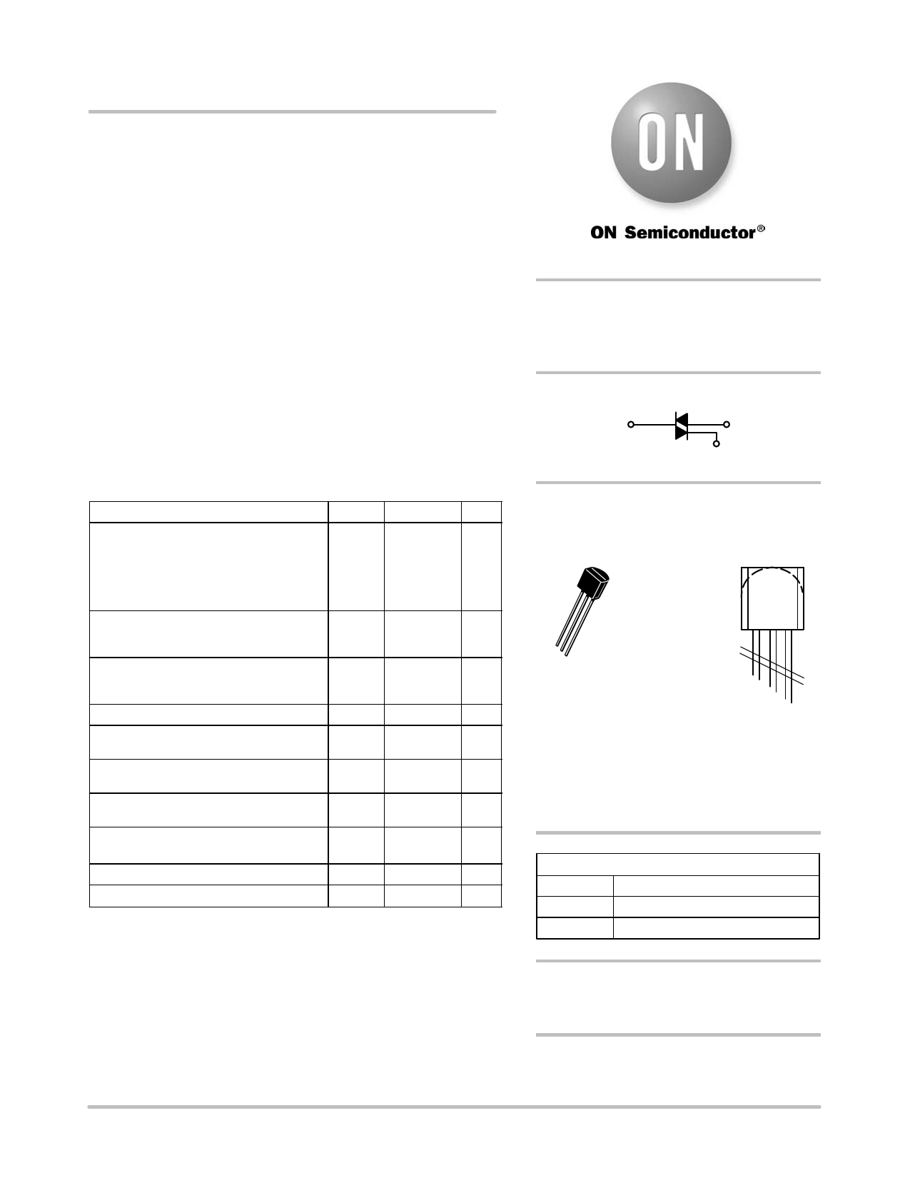
| Descripción | (MAC97 Series) Sensitive Gate Triacs Silicon Bidirectional Thyristors | |
| Fabricantes | ON Semiconductor | |
| Logotipo | ||
Hay una vista previa y un enlace de descarga de MAC97A4 (archivo pdf) en la parte inferior de esta página. Total 8 Páginas | ||
|
No Preview Available !
www.DataSheet4U.com
MAC97 Series
Preferred Device
Sensitive Gate Triacs
Silicon Bidirectional Thyristors
Designed for use in solid state relays, MPU interface, TTL logic and
any other light industrial or consumer application. Supplied in an
inexpensive TO−92 package which is readily adaptable for use in
automatic insertion equipment.
Features
• One−Piece, Injection−Molded Package
• Blocking Voltage to 600 Volts
• Sensitive Gate Triggering in Four Trigger Modes (Quadrants) for all
possible Combinations of Trigger Sources, and especially for Circuits
that Source Gate Drives
• All Diffused and Glassivated Junctions for Maximum Uniformity of
Parameters and Reliability
• Pb−Free Packages are Available*
http://onsemi.com
TRIACS
0.8 AMPERE RMS
200 thru 600 VOLTS
MT2
MT1
G
MAXIMUM RATINGS (TJ = 25°C unless otherwise noted)
Rating
Symbol
Value
Unit
Peak Repetitive Off-State Voltage
(TJ = −40 to +110°C) (Note 1)
Sine Wave 50 to 60 Hz, Gate Open
MAC97A4
MAC97A6
MAC97A8
VDRM,
VRRM
200
400
600
V
On-State RMS Current
Full Cycle Sine Wave 50 to 60 Hz
(TC = +50°C)
Peak Non−Repetitive Surge Current
One Full Cycle, Sine Wave 60 Hz
(TC = 110°C)
Circuit Fusing Considerations (t = 8.3 ms)
IT(RMS)
ITSM
I2t
0.6
8.0
0.26
A
A
A2s
Peak Gate Voltage
(t v 2.0 ms, TC = +80°C)
VGM 5.0 V
Peak Gate Power
(t v 2.0 ms, TC = +80°C)
PGM 5.0 W
Average Gate Power
(TC = 80°C, t v 8.3 ms)
PG(AV)
0.1
W
Peak Gate Current
(t v 2.0 ms, TC = +80°C)
IGM 1.0 A
Operating Junction Temperature Range
TJ −40 to +110 °C
Storage Temperature Range
Tstg −40 to +150 °C
Maximum ratings are those values beyond which device damage can occur.
Maximum ratings applied to the device are individual stress limit values (not
normal operating conditions) and are not valid simultaneously. If these limits are
exceeded, device functional operation is not implied, damage may occur and
reliability may be affected.
1. VDRM and VRRM for all types can be applied on a continuous basis. Blocking
voltages shall not be tested with a constant current source such that the
voltage ratings of the devices are exceeded.
*For additional information on our Pb−Free strategy and soldering details, please
download the ON Semiconductor Soldering and Mounting Techniques
Reference Manual, SOLDERRM/D.
MARKING
DIAGRAMS
1
23
TO−92 (TO−226AA)
CASE 029
STYLE 12
MAC
97Ax
AYWWG
G
MAC97Ax
A
Y
WW
G
= Device Code
x = 4, 6, or 8
= Assembly Location
= Year
= Work Week
= Pb−Free Package
(Note: Microdot may be in either location)
PIN ASSIGNMENT
1 Main Terminal 1
2 Gate
3 Main Terminal 2
ORDERING INFORMATION
See detailed ordering and shipping information in the package
dimensions section on page 6 of this data sheet.
Preferred devices are recommended choices for future use
and best overall value.
© Semiconductor Components Industries, LLC, 2005
September, 2005 − Rev. 9
1
Publication Order Number:
MAC97/D
1 page 
MAC97 Series
1.0 10
ZQJC(t) = RQJC(t) @ r(t)
0.1
0.01
0.1
1.0
10 100
t, TIME (ms)
1S103
1S104
Figure 5. Transient Thermal Response
100
10 Q4
Q3
Q2
Q1
1
0
−40 −25 −10 5 20 35 50 65 80
TJ, JUNCTION TEMPERATURE (°C)
95 110
Figure 7. Typical Gate Trigger Current versus
Junction Temperature
100
5.0
3.0
2.0
TJ = 110°C
f = 60 Hz
CYCLE
1.0
1.0
Surge is preceded and followed by rated current.
2.0 3.0 5.0
10
30
NUMBER OF CYCLES
50
100
Figure 6. Maximum Allowable Surge Current
1.2
1.1 Q4
1.0 Q3
0.9 Q2
0.8 Q1
0.7
0.6
0.5
0.4
0.3
−40 −25
−10 5 20 35 50 65 80
TJ, JUNCTION TEMPERATURE (°C)
95 110
Figure 8. Typical Gate Trigger Voltage versus
Junction Temperature
10
10 Q2
MT2 Negative
Q4 Q3
1
MT2 Positive
1
Q1
0
−40 −25
−10 5 20 35 50 65 80
TJ, JUNCTION TEMPERATURE (°C)
95 110
Figure 9. Typical Latching Current versus
Junction Temperature
0.1
−40 −25
−10 5 20 35 50 65 80
TJ, JUNCTION TEMPERATURE (°C)
95 110
Figure 10. Typical Holding Current versus
Junction Temperature
http://onsemi.com
5
5 Page | ||
| Páginas | Total 8 Páginas | |
| PDF Descargar | [ Datasheet MAC97A4.PDF ] | |
Hoja de datos destacado
| Número de pieza | Descripción | Fabricantes |
| MAC97A | Silicon Bidirectional Triode Thyristors | TGS |
| MAC97A1 | Thyristor TRIAC 600V 8A 3-Pin TO-92 Tape and Ammo | New Jersey Semiconductor |
| MAC97A2 | Thyristor TRIAC 600V 8A 3-Pin TO-92 Tape and Ammo | New Jersey Semiconductor |
| MAC97A3 | Thyristor TRIAC 600V 8A 3-Pin TO-92 Tape and Ammo | New Jersey Semiconductor |
| Número de pieza | Descripción | Fabricantes |
| SLA6805M | High Voltage 3 phase Motor Driver IC. |
Sanken |
| SDC1742 | 12- and 14-Bit Hybrid Synchro / Resolver-to-Digital Converters. |
Analog Devices |
|
DataSheet.es es una pagina web que funciona como un repositorio de manuales o hoja de datos de muchos de los productos más populares, |
| DataSheet.es | 2020 | Privacy Policy | Contacto | Buscar |