|
|
|
PDF L3914A Data sheet ( Hoja de datos )
| Número de pieza | L3914A | |
| Descripción | (L3914A - L3934A) SPEECH AND 14 MEMORY DIALER | |
| Fabricantes | ST Microelectronics | |
| Logotipo | ||
Hay una vista previa y un enlace de descarga de L3914A (archivo pdf) en la parte inferior de esta página. Total 15 Páginas | ||
|
No Preview Available !
www.DataSheet4U.com
L3914A
L3924A - L3934A
SPEECH AND 14 MEMORY DIALER WITH HOLD FUNCTION
ADVANCE DATA
SPEECH CIRCUIT
2 TO 4 WIRES CONVERSION
PRESENT THE PROPER DC PATH FOR THE
LINE CURRENT AND THE FLEXIBILITY TO
ADJUST IT AND ALLOW PARALLEL PHONE
OPERATION
PROVIDES SUPPLY WITH LIMITED CUR-
RENT FOR EXTERNAL CIRCUITRY
SYMMETRICAL HIGH IMPEDANCE MICRO-
PHONE INPUTS SUITABLE FOR DYNAMIC
ELECTRET OR PIEZOELECTRIC
TRANSDUCER
ASYMMETRICAL EARPHONE OUTPUT
SUITABLE FOR DYNAMIC TRANSDUCER
LINE LOSS COMPENSATION
INTERNAL MUTING TO DISABLE SPEECH
DURING DIALING
HOLD FUNCTION FOR PARALLEL PHONE
WITH 400ms DELAY TO PREVENT FALSE
RELEASE
DIALER CIRCUIT
32 DIGITS FOR LAST NUMBER REDIAL
BUFFER
18 DIGITS FOR 13 MEMORY REDIAL
ALLOW MIXED MODE DIALING IN EITHER
TONE OR PULSE MODE
PACIFIER TONE PROVIDES AUDIBLE INDI-
CATION OF VALID KEY PRESSED IN A
BUZZER OR/AND IN THE EARPHONE
TIMED PABX PAUSE
FLASH INITIATES TIMED BREAK:
MASK OPTIONS WITH 585ms,300ms,100ms
CONTINUOUS TONE FOR EACH DIGIT UN-
TIL KEY RELEASE
USES INEXPENSIVE 3.579545MHz CE-
RAMIC RESONATOR
POWERED FROM TELEPHONE LINE, LOW
OPERATING VOLTAGE FOR LONG LOOP
APPLICATION
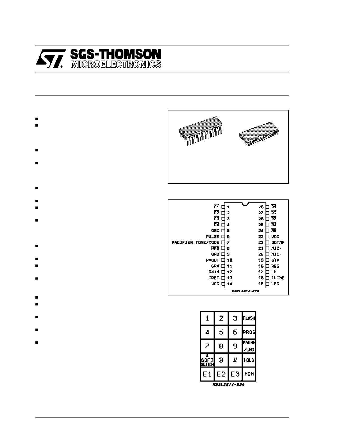
DIP28
SO28
ORDERING NUMBERS:
L3914AN
L3914AD
L3924AN
L3924AD
L3934AN
L3934AD
PIN CONNECTION (Top view)
KEYPAD CONFIGURATION
DESCRIPTION
The device consists of the speech and the dialer.
It provides the DC line interface circuit that termi-
nates the telephone line, analog amplifier for
speech transmission and necessary signals for
either DTMF or loop disconnect (pulse) dialing.
Note: PAUSE/LND:
PAUSE and LND functions are sharing the same key with different
sequence. Hereafter, PAUSE and LND keys arereferring to the same
key.
January 1995
1/15
This is advanced information on a new product now in development or undergoing evaluation. Details are subject to change without notice.
1 page 
L3914A - L3924A - L3934A
FUNCTION PIN DESCRIPTION (continued)
To dial a number from repertory memory (HKS
must be low), enter the following:
MEM (Location 0-9) or E1-E3
To save the last number dialed, enter the follow-
ing:
PROG MEM (location 0-9) or E1-E3
HOOK FLASH
D1 FLASH D2 ...etc
Hook flash may be entered into the dialed se-
quence at any point by keying in the function key,
FLASH. Flash consists of a timed break of
585ms, 300ms or 100ms depending on the Mask
option. When a FLASH key is pressed, no further
key inputs will be accepted until the hookflash
function has been dialed. The key input following
a FLASH will be stored as the initial digit of the
new number, overwriting the number dialed be-
fore the FLASH, unless it is another FLASH.
FLASH key pressed immediately after hookswitch
or LND will not clear the LND buffer unless digits
are entered following the FLASH key.
Example:
FLASH
LND not cleared
LND FLASH
LND not cleared
LND FLASH D1 D2
LND buffer will contain D1, D2
PAUSE/LAST NUMBER DIALED
If the PAUSE/LND key is pressed right after off
hook or FLASH key, it is considered as LND, if it
is pressed after a digit, it will be considered as
PAUSE.
LAST NUMBERED DIALED
OFF-HOOK PAUSE/LND or FLASH PAUSE/LND
Last number dialing is accomplished by entering
the PAUSE/LND key.
PAUSE
OFF-HOOK D1 PAUSE/LND D2 ...etc
A pause may be entered into the dialed sequence
at any point by keying in the special function key,
PAUSE/LND. Pause inserts a 3.1 second delay into
the dialing sequence. The total delay, including pre-
digit and post-digit pauses is shown in Table 3.
Table 3: Special Function Delays
Each delay shown below represents the time re-
quired after the special function key is depressed
until a new digit is dialed. The time is considered
”FIRST” key if all previous inputs have been com-
pletely dialed. The time is considered ”AUTO” if in
redial, or if previous dialling is still in progress.
Function First/Auto
SOFTSWITC H
PAUSE
FIRST
AUTO
FIRST
AUTO
Delay (seconds)
Pulse
To ne
0.2
1.0
2.6 3.0
3.4 3.1
HOLD
When HOLD key is pressed during off hook, there
are two options. The first option is to mute the
phone (LED will blink) and the conversation can
be resumed by pressing the HOLD key again.
The second option is to mute the phone (LED will
blink), on-hook the phone (LED will still blink at
1Hz frequency) and automatic switch off the
phone when parallel phone is off-hook.
The HOLD function is disabled when the line cur-
rent drops below 20mA.
SOFTSWITCH FUNCTION USING TONE/PULSE
MODE SWITCH
When dialing in Pulse mode after off-hook, switch-
ing TONE/PULSE mode switch from Pulse to Tone
will cause the device to change the signaling mode
into tone signal and store the softswitch function in
the LND memory for redial. To redial the softswitch
function (mixed mode dialing) in the pulse mode af-
ter going on-hook and back to off-hook, you have
to switch the TONE/PULSE mode switch back to
pulse mode either before going on-hook or after off-
hook or during on-hook.
Subsequentmode change from Tone to Pulse will
change the signaling mode to pulse dialing se-
quence but this mode change will not be stored in
.the LND memory.
When dialing in Tone mode after off-hook, a switch-
ing of TONE/PULSE mode Switch from Tone to
Pulse will cause the device to change the signaling
mode into pulse mode but this mode change will
not be stored in the LND memory. When LND key
is pressed in Tone mode after going off-hook, the
device will output all tone signals.
A pacifier tone of 75ms is provided after 32ms
deboun ce time when switching from Pulse to
Tone mode.
Redial by the LND key will repeat the mixed dial-
ing sequence in Pulse mode.
5/15
5 Page 
TEST CIRCUITS(continued)
Figure 7.
470nF
2.25K GDTMF
22
4.0V
22nF
VMF
IDD
RDTMF
VDD
470K
PULSE
3.58MHz
OSC
PULSE
TONE
SW2 MODE
100K /PT
HKS
SW1
GND
300Ω 10µF
Re
Vear
RXOUT
100K GRX
RGRX
IREF
3.6K
VCC
100µF
RGIN
23
6
5
7
8
9
10
11
13
14
12
620Ω
100nF
Figure 8.
470nF
2.25K
GDTMF
22
IDD 22nF
4.0V
470K
3.58MHz
SW2
PULSE
TONE
100K
SW1
RP
Re 10µF
RGRX
Vear
3.6K
100µF
VDD
PULSE
OSC
MODE
/PT
HKS
GND
23
6
5
7
8
9
RXOUT
GRX
10
11
IREF
13
VCC
RGIN
14
12
620Ω
Vinp
100nF
L3914A - L3924A - L3934A
C4
4
C3
3
C2
2
C1
1
28 R1
R2
27
R3
26
R4
25
R5
24
VLN
GDTMF=20log
VMF
Vear
CDTMF=20log
VLN
1 2 3 FLASH
4 5 6 PROG
7 8 9 P/LND
* 0 # HOLD
E1 E2 E3 MEM
MIC+
21
2.2K
1µF
MIC-
20
GTX
19
1µF
RGTX 88K 4.7µF
REG
18
LN
17
VLN
LED
15
ILED
16 ILINE 390Ω
130K
3.9K
100µF
IL
20Ω 390Ω
600Ω
D95TL173
C4
4
C3
3
C2
2
C1
1
R1
28
R2
27
R3
26
25 R4
R5
24
Vear
GRX=20log
Vinp
NRX with Vin=0
1 2 3 FLASH
4 5 6 PROG
7 8 9 P/LND
* 0 # HOLD
E1 E2 E3 MEM
MIC+
21
2.2K
1µF
MIC-
20
GTX
19
1µF
RGTX
REG
18
LN
17
4.7µF
VLN
LED
15
ILED
16
ILINE
390Ω
130K
3.9K
100µF
IL
20Ω 390Ω
D95TL167
11/15
11 Page | ||
| Páginas | Total 15 Páginas | |
| PDF Descargar | [ Datasheet L3914A.PDF ] | |
Hoja de datos destacado
| Número de pieza | Descripción | Fabricantes |
| L3914A | (L3914A - L3934A) SPEECH AND 14 MEMORY DIALER | ST Microelectronics |
| Número de pieza | Descripción | Fabricantes |
| SLA6805M | High Voltage 3 phase Motor Driver IC. |
Sanken |
| SDC1742 | 12- and 14-Bit Hybrid Synchro / Resolver-to-Digital Converters. |
Analog Devices |
|
DataSheet.es es una pagina web que funciona como un repositorio de manuales o hoja de datos de muchos de los productos más populares, |
| DataSheet.es | 2020 | Privacy Policy | Contacto | Buscar |