|
|
|
PDF U2642B Data sheet ( Hoja de datos )
| Número de pieza | U2642B | |
| Descripción | Intermittent- and Wipe/Wash Control | |
| Fabricantes | TEMIC Semiconductors | |
| Logotipo | ||
Hay una vista previa y un enlace de descarga de U2642B (archivo pdf) en la parte inferior de esta página. Total 10 Páginas | ||
|
No Preview Available !
www.DataSheet4U.com
U2642B
Intermittent- and Wipe/Wash Control for Wiper Systems
Description
With the U264xB, TEMIC Semiconductors developed a
family of intermittent- and wipe/wash control circuits for
windshield or backlite wiper systems with identical basic
functions. The circuit design provides the possibility to
generate ”x” versions using different metallization
masks. Thus, it is easy to verify a broad range of time se-
quences which can be set independently of each other.
Features
D Relay activation can be controlled by a limit switch of
the wiper motor or by a fixed activation period for
systems without limit switch
D Debounced input stages
D Enable/disable of pre-wash delay by program pin
D Polarity of WIWA: VBatt
D Polarity of INT: VBatt
D Relay output is protected with a clamping diode
D Relay activation: 0.64 s
D Interval pause:
10 s
D After wiping:
5.8 s
D Pre-wash delay: 0.91 s
D Wipe/wash mode with priority
D Protected in accordance to ISO/TR 7637–1
D EMC with intergrated filters
Ordering Information
Extended Type Number
U2642B
U2642B–FP
Package
DIP8
SO8
Remarks
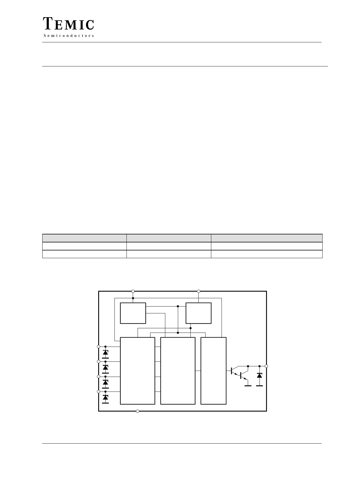
Block Diagram
VS
OSC
Voltage
stabilization
and
POR
Oscillator
INT
WIWA
LS
PP
21 V
21 V Input
comparator
21 V
21 V
GND
TELEFUNKEN Semiconductors
Rev. A2, 02-Dec-97
Logic
Load-
dump
detection
and
output
control
Open-collector
relay driver
21 V
REL
Figure 1.
13944
1 (10)
1 page 
U2642B
Parameters
Test Conditions / Pin Symbol Min Typ Max Unit
Inputs INT, WIWA and PP
Pins 1, 2 and 4
Internal protection-diode
voltage
Internal capacitor
Switching threshold
voltage
Input current
Internal pull-down resistor
External protection resistor
Relay Output
IE = 10 mA
VE = 0 V
Pins 6
VE 19.5 21.0 25.5 V
CE 25 pF
VE 0.375 VS 0.5 VS 0.675 VS V
–IE 1 m A
RE 13 20 27 kW
RS 10
kW
Saturation voltage
Saturation voltage
Z-diode clamp voltage
Leakage current
Relay coil resistance
Load-dump protection
threshold
Internal pulse times
I = 100 mA
I = 200 mA
I = 10 mA
V = 14 V
VREL
1.1 V
VREL
1.5 V
VREL
19.5
21.0
25.5
V
IREL 12 m A
RREL
60
W
VBatt
28
33
42
V
Debouncing period inputs INT/WIWA 12 - 16 clocks
tD
60
70
80 ms
Debouncing period inputs LS
3 – 4 clocks
tDL
15
17.5
20
ms
Relay activation time
96 clocks tON 480 ms
Intermittent pause
After wiping period
" tINT 5.92
1024 68 clocks tWIWA
4.78
5.46
s
s
Pre-wash delay reaction
time for switch-on delay =
88 – 96 clocks tDEL
440
480 ms
tDEL + tD
Note: All internally generated time sequences are derived from the oscillator frquency. The tolerances refer to a
frequency adjusted to fOSC = 200 Hz.
TELEFUNKEN Semiconductors
Rev. A2, 02-Dec-97
5 (10)
5 Page | ||
| Páginas | Total 10 Páginas | |
| PDF Descargar | [ Datasheet U2642B.PDF ] | |
Hoja de datos destacado
| Número de pieza | Descripción | Fabricantes |
| U2642B | Intermittent- and Wipe/Wash Control | TEMIC Semiconductors |
| Número de pieza | Descripción | Fabricantes |
| SLA6805M | High Voltage 3 phase Motor Driver IC. |
Sanken |
| SDC1742 | 12- and 14-Bit Hybrid Synchro / Resolver-to-Digital Converters. |
Analog Devices |
|
DataSheet.es es una pagina web que funciona como un repositorio de manuales o hoja de datos de muchos de los productos más populares, |
| DataSheet.es | 2020 | Privacy Policy | Contacto | Buscar |