|
|
|
PDF SC1470 Data sheet ( Hoja de datos )
| Número de pieza | SC1470 | |
| Descripción | Synchronous Buck Power Supply Controller | |
| Fabricantes | SEMTECH ELECTRONICS | |
| Logotipo | ||
Hay una vista previa y un enlace de descarga de SC1470 (archivo pdf) en la parte inferior de esta página. Total 21 Páginas | ||
|
No Preview Available !
www.DataSheet4U.com
POWER MANAGEMENT
Description
The SC1470 is a single output, constant on-time
synchronous-buck, pseudo fixed frequency, PWM
controller intended for use in notebook computers and
other battery operated portable devices. Features
include high efficiency and fast dynamic response with
no minimum on time. The excellent transient response
means that SC1470 based solutions will require less
output capacitance than competing fixed frequency
converters.
The frequency is constant until a step in load or line voltage
occurs, at which time the pulse density and frequency
will increase or decrease to counter the change in output
or input voltage. After the transient event, the controller
frequency will return to steady state operation. At light
loads, Power-Save Mode enables the SC1470 to skip
PWM pulses for better efficiency.
The output voltage can be adjusted from 0.5V to VCCA.
The integrated gate drivers feature adaptive shoot-
through protection and soft switching. Additional features
include cycle-by-cycle current limit, digital soft-start, over-
voltage and under-voltage protection, and a PGOOD
output.
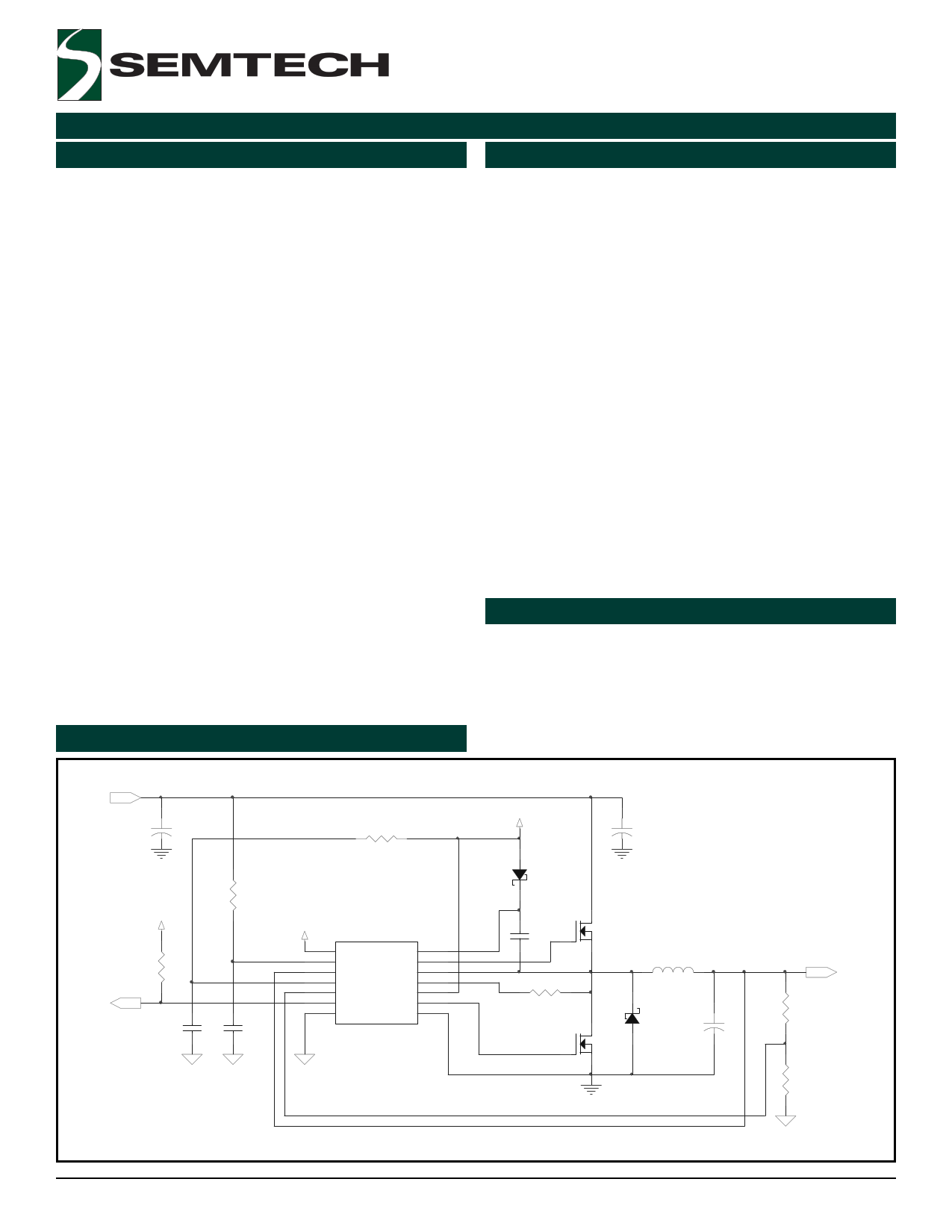
Typical Application Circuit
SC1470
Synchronous Buck
Power Supply Controller
Features
Constant on-time for fast dynamic response
Programmable VOUT range = 0.5 – VCCA
VIN range = 1.8V – 25V
DC current sense using low-side RDS(ON)
Sensing or RSENSE in source of low-side
MOSFET for greater accuracy
Resistor programmable frequency
Cycle-by-Cycle current limit
Digital soft-start
Combined EN and PSAVE functions
Over-voltage/under-voltage fault protection and
PGOOD output
5uA typical shutdown current
Low quiescent power dissipation
14 Lead TSSOP package
Industrial temperature range
1% Internal reference
Integrated gate drivers with soft switching
Efficiency > 90%
Applications
Notebook computers
CPU I/O supplies
Handheld terminals and PDAs
LCD monitors
Network power supplies
1.8V - 25V
+
C1
PGOOD
+5V
R3
C5
R1
R2
+5V U1
1
2
3
4
5
6
7
EN/PSV
TON
VOUT
VCCA
FBK
PGOOD
GND
BST
DH
LX
ILIM
VDDP
DL
PGND
14
13
12
11
10
9
8
C6
SC1470
+5V
D1
C3
R4
+
C2
Q1
L1
D2
Q2
+
C4
0.5V - 5.5V
R5
R6
Revision: October 14, 2004
1
www.semtech.com
1 page 
SC1470
POWER MANAGEMENT
Pin Configuration
Top View
EN/PSV 1
TON 2
VOUT 3
VCCA 4
FBK 5
PGOOD 6
AGND 7
14 BST
13 DH
12 LX
11 ILIM
10 VDDP
9 DL
8 PGND
Ordering Information
DEVICE (1)
PACKAGE
SC1470ITSTR
TSSOP-14
SC1470ITSTRT(2)
TSSOP-14
SC1470EVB
EVALUATION BOARD
Notes:
(1) Only available in tape and reel packaging. A reel
contains 2500 devices.
(2) Lead free option. This product is fully WEEE and RoHS
compliant.
TSSOP-14
Pin Descriptions
Pin # Pin Name Pin Function
1 EN/PSV Enable/Power Save input . Tie to ground to disable SMPS. Tie to +5V to enable SMPS and
activate PSAVE mode. Float to enable SMPS and activate continous conduction mode.
2 TON On-time set input. Sets on-time of upper MOSFET via series resistor to the input supply.
3 VOUT Output voltage sense input. Connect to the output of the SMPS.
4 VCCA Supply voltage input for the analog supply. Connect through an RC filter to +5V.
5 FBK Feedback input. Connect from a resistor divider at output of the SMPS to select output voltage.
6 PGOOD Power Good open drain NMOS output. Goes high after a fixed clock cycle delay following power
up.
7 AGND Analog ground.
8 PGND Power ground.
9 DL Gate drive output for the low side MOSFET switch.
10 VDDP +5V supply voltage input for the gate drivers.
11 ILIM Current limit input. Connect to drain of low-side MOSFET for RDS(on) sensing or the source for
resistor sensing through a threshold sensing resistor. See applications section for more
information.
12 LX Switching node inductor connection.
13 DH Gate drive output for the high side MOSFET switch.
14 BST
2004 Semtech Corp.
Boost capacitor connection for the high side gate drive.
5
www.semtech.com
5 Page 
SC1470
POWER MANAGEMENT
Applications Information (Cont.)
Stability Considerations:
Unstable operation shows up in two related but distinctly
different ways: double pulsing and fast-feedback loop
instability.
Double-pulsing occurs due to noise on the output or be-
cause the ESR is too low, causing not enough voltage
ramp in the output signal. This causes the error amplifier
to trigger prematurely after the 400ns minimum off-time
has expired. Double-pulsing will result in higher ripple
voltage at the output, but in most cases is harmless.
However, in some cases double-pulsing can indicate the
presence of loop instability, which is caused by insuffi-
cient ESR. One simple way to solve this problem is to add
some trace resistance in the high current output path. A
side effect of doing this is output voltage droop with load.
Another way to eliminate doubling-pulsing is to add a ca-
pacitor across the upper feedback resistor divider net-
work. This is shown below in Figure 5, by capacitor C4 in
the schematic. This capacitance should be left out until
confirmation that double-pulsing exists. Adding this ca-
pacitance will add a zero in the transfer function and
should eliminate the problem. It is best to leave a spot
on the PCB in case it is needed.
SC1470 ESR Requirements
Constant on-time control used in the SC1470 regulates
the ripple voltage at the output capacitor. This signal
consists of a term generated by the output ESR of the
capacitor and a term based on the increase in voltage
across the capacitor due to charging and discharging
during the switching cycle. The minimum ESR is set to
generate the required ripple voltage for regulation. For
most applications the minimum ESR ripple voltage is
dominated by PCB layout and the properties of SP or
POSCAP type output capacitors. For applications using
ceramic output capacitors the absolute minimum ESR
must be considered. Existing literature describing the ESR
requirements to prevent double pulsing does not
accurately predict the performance of constant on-time
controllers. A time domain model of the converter was
developed to generate equations for the minimum ESR
empirically. If the ESR is low enough the ripple voltage is
dominated by the charging of the output capacitor. This
ripple voltage lags the on-time due to the LC poles and
can cause double pulsing if the phase delay exceeds the
off-time of the converter. Referring to Figure 5, the
equation for the minimum ESR as a function of output
capacitance, switching frequency and duty cycle is;
+5V +VIN
+
D1 C1
ESR
>
R2+R3
R3
•
1
+3
•
Fs
-
200000
Fs
2• π•Cout •Fs •( 1 −D)
2
BST
DH
LX
ILIM
VDDP
DL
PGND
14
13
12
11
10
9
8
SC1470
Q1
C2
Where D = Vout/Vin. Plugging in the numbers for this
L1 0.5V - 5.5V design ESR > 0.023 ohms. With the capacitors chosen
the total ESR of 0.025 ohms plus the board trace resis-
R1
D2
Q2
+
C3
FBK
R2 C4
10pF
tance meet the requirement.
R3
FIGURE 5
Input Capacitor Selection
Input capacitors are selected based upon the input ripple
current demand of the converter. First determine the
input ripple current expected and then choose a capacitor
to meet that demand.
Loop instability can result in oscillations at the output
after line or load perturbations that can trip the overvolt-
age protection latch or cause the output voltage to fall
below the tolerance limit.
The best way for checking stability is to apply a zero to
full load transient and observe the output voltage ripple
envelope for overshoot and ringing. Over one cycle of
ringing after the initial step is sign that the ESR should
be increased.
The input RMS ripple current can be calculated as
follows:
IRMS =
VOUT
•
(VIN
−
VOUT
)
•
IOUT
VIN
Therefore, for a maximum load current of 6.0A , the input
capacitors should be able to safely handle 3A of ripple
current. For the EVAL board, we chose two 10uF, 25V
ceramic capacitors. Each capacitor has a ripple current
capability of 2A.
2004 Semtech Corp.
11
www.semtech.com
11 Page | ||
| Páginas | Total 21 Páginas | |
| PDF Descargar | [ Datasheet SC1470.PDF ] | |
Hoja de datos destacado
| Número de pieza | Descripción | Fabricantes |
| SC147 | (SCxxx) Triacs | Digitron Electronic |
| SC147 | Thyristor TRIAC 200V 120A 3-Pin(3+Tab) TO-220AB | New Jersey Semiconductor |
| SC1470 | Synchronous Buck Power Supply Controller | SEMTECH ELECTRONICS |
| SC1471 | Power Supply Controller | Semtech Corporation |
| Número de pieza | Descripción | Fabricantes |
| SLA6805M | High Voltage 3 phase Motor Driver IC. |
Sanken |
| SDC1742 | 12- and 14-Bit Hybrid Synchro / Resolver-to-Digital Converters. |
Analog Devices |
|
DataSheet.es es una pagina web que funciona como un repositorio de manuales o hoja de datos de muchos de los productos más populares, |
| DataSheet.es | 2020 | Privacy Policy | Contacto | Buscar |