|
|
|
PDF NID5001N Data sheet ( Hoja de datos )
| Número de pieza | NID5001N | |
| Descripción | Self-protected FET | |
| Fabricantes | ON Semiconductor | |
| Logotipo | ||
Hay una vista previa y un enlace de descarga de NID5001N (archivo pdf) en la parte inferior de esta página. Total 6 Páginas | ||
|
No Preview Available !
www.DataSheet4U.com
NID5001N
Preferred Device
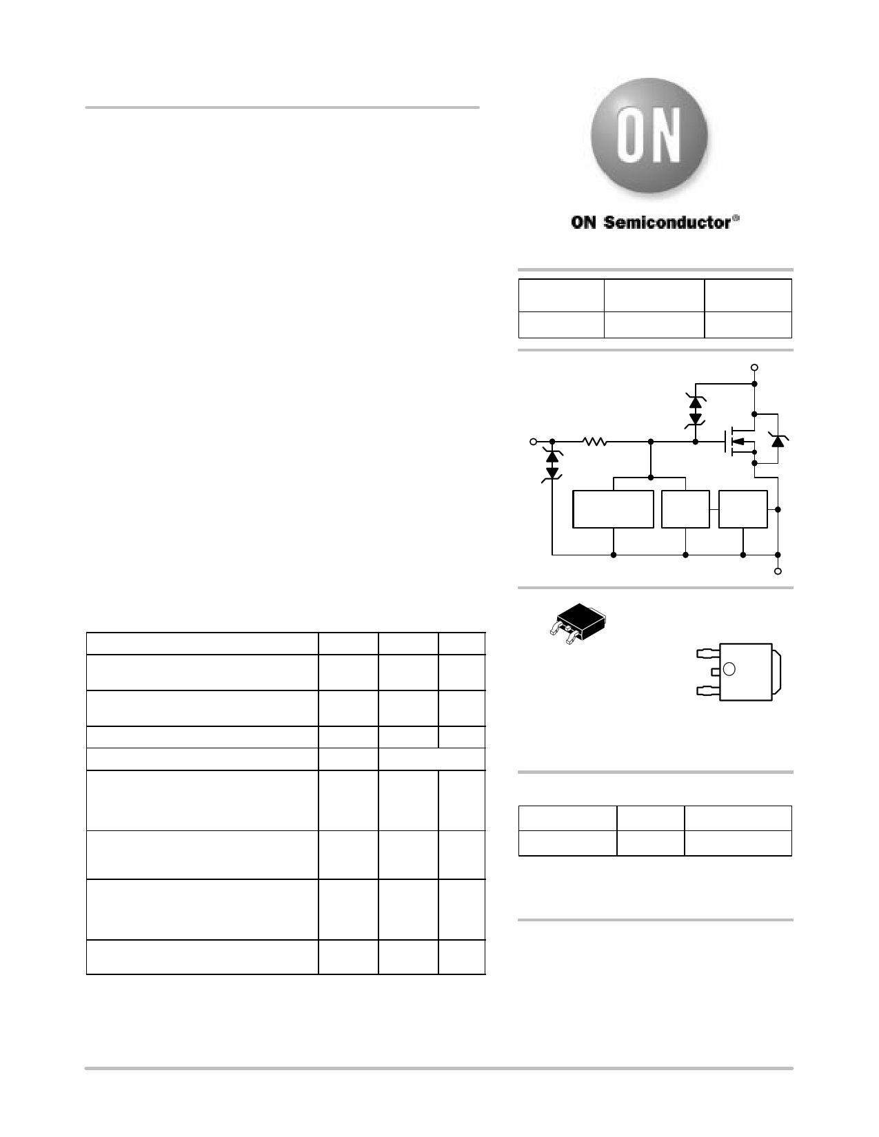
Self−protected FET
with Temperature and
Current Limit
HDPlus devices are an advanced series of power MOSFETs which
utilize ON Semicondutor’s latest MOSFET technology process to
achieve the lowest possible on−resistance per silicon area while
incorporating smart features. Integrated thermal and current limits
work together to provide short circuit protection. The devices feature
an integrated Drain−to−Gate Clamp that enables them to withstand
high energy in the avalanche mode. The Clamp also provides
additional safety margin against unexpected voltage transients.
Electrostatic Discharge (ESD) protection is provided by an integrated
Gate−to−Source Clamp.
Features
• Low RDS(on)
• Current Limitation
• Thermal Shutdown with Automatic Restart
• Short Circuit Protection
• IDSS Specified at Elevated Temperature
• Avalanche Energy Specified
• Slew Rate Control for Low Noise Switching
• Overvoltage Clamped Protection
MOSFET MAXIMUM RATINGS (TJ = 25°C unless otherwise noted)
Rating
Symbol Value Unit
Drain−to−Source Voltage Internally
Clamped
VDSS
42 Vdc
Drain−to−Gate Voltage Internally Clamped
(RGS = 1.0 MW)
Gate−to−Source Voltage
Drain Current
Continuous
Total Power Dissipation
@ TA = 25°C (Note 1)
@ TA = 25°C (Note 1)
@ TA = 25°C (Note 2)
Thermal Resistance − Junction−to−Case
Junction−to−Ambient (Note 1)
Junction−to−Ambient (Note 2)
Single Pulse Drain−to−Source Avalanche
Energy
(VDD = 25 Vdc, VGS = 5.0 Vdc,
IL = 4.5 Apk, L = 120 mH, RG = 25 W)
Operating and Storage Temperature
Range
VDGR
VGS
ID
PD
RqJC
RqJA
RqJA
EAS
TJ, Tstg
42 Vdc
"14
Vdc
Internally Limited
W
64
1.0
1.56
1.95 °C/W
120
80
1215
mJ
−55 to
150
°C
1. Minimum FR4 PCB, steady state.
2. Mounted onto a 2″ square FR4 board (1″ square, 2 oz. Cu 0.06″ thick
single−sided, t = steady state).
http://onsemi.com
VDSS
(Clamped)
42 V
RDS(ON) TYP
23 mΩ @ 10 V
ID MAX
(Limited)
33 A*
Drain
Gate
Input
Overvoltage
Protection
RG
ESD Protection
MPWR
Temperature Current Current
Limit
Limit Sense
Source
DPAK
CASE 369C
STYLE 2
MARKING
DIAGRAM
1 YWW
2 X NID
5001N
3
NID5001N = Device Code
Y = Year
WW = Work Week
1 = Gate
2 = Drain
3 = Source
ORDERING INFORMATION
Device
Package
Shipping†
NID5001NT4
DPAK 2500/Tape & Reel
†For information on tape and reel specifications,
including part orientation and tape sizes, please
refer to our Tape and Reel Packaging Specification
Brochure, BRD8011/D.
Preferred devices are recommended choices for future use
and best overall value.
*Max current may be limited below this value
depending on input conditions.
© Semiconductor Components Industries, LLC, 2004
January, 2004 − Rev. 6
1
Publication Order Number:
NID5001N/D
1 page 
NID5001N
PACKAGE DIMENSIONS
B
VR
DPAK
CASE 369C−01
ISSUE O
−T−
SEATING
PLANE
C
E
S
F
4
1 23
A
K
J
LH
D 2 PL
G 0.13 (0.005) M T
U
Z
SOLDERING FOOTPRINT*
6.20
0.244
2.58
0.101
3.0
0.118
5.80
0.228
1.6 6.172
0.063 0.243
INCHES
DIM MIN MAX
A 0.235 0.245
B 0.250 0.265
C 0.086 0.094
D 0.027 0.035
E 0.018 0.023
F 0.037 0.045
G 0.180 BSC
H 0.034 0.040
J 0.018 0.023
K 0.102 0.114
L 0.090 BSC
R 0.180 0.215
S 0.025 0.040
U 0.020 −−−
V 0.035 0.050
Z 0.155 −−−
MILLIMETERS
MIN MAX
5.97 6.22
6.35 6.73
2.19 2.38
0.69 0.88
0.46 0.58
0.94 1.14
4.58 BSC
0.87 1.01
0.46 0.58
2.60 2.89
2.29 BSC
4.57 5.45
0.63 1.01
0.51 −−−
0.89 1.27
3.93 −−−
STYLE 2:
PIN 1. GATE
2. DRAIN
3. SOURCE
4. DRAIN
ǒ ǓSCALE 3:1
mm
inches
*For additional information on our Pb−Free strategy and soldering
details, please download the ON Semiconductor Soldering and
Mounting Techniques Reference Manual, SOLDERRM/D.
http://onsemi.com
5
5 Page | ||
| Páginas | Total 6 Páginas | |
| PDF Descargar | [ Datasheet NID5001N.PDF ] | |
Hoja de datos destacado
| Número de pieza | Descripción | Fabricantes |
| NID5001N | Self-protected FET | ON Semiconductor |
| Número de pieza | Descripción | Fabricantes |
| SLA6805M | High Voltage 3 phase Motor Driver IC. |
Sanken |
| SDC1742 | 12- and 14-Bit Hybrid Synchro / Resolver-to-Digital Converters. |
Analog Devices |
|
DataSheet.es es una pagina web que funciona como un repositorio de manuales o hoja de datos de muchos de los productos más populares, |
| DataSheet.es | 2020 | Privacy Policy | Contacto | Buscar |