|
|
|
PDF NCP5318 Data sheet ( Hoja de datos )
| Número de pieza | NCP5318 | |
| Descripción | Two/Three/Four-Phase Buck CPU Controller | |
| Fabricantes | ON Semiconductor | |
| Logotipo | ||
Hay una vista previa y un enlace de descarga de NCP5318 (archivo pdf) en la parte inferior de esta página. Total 31 Páginas | ||
|
No Preview Available !
www.DataSheet4U.com
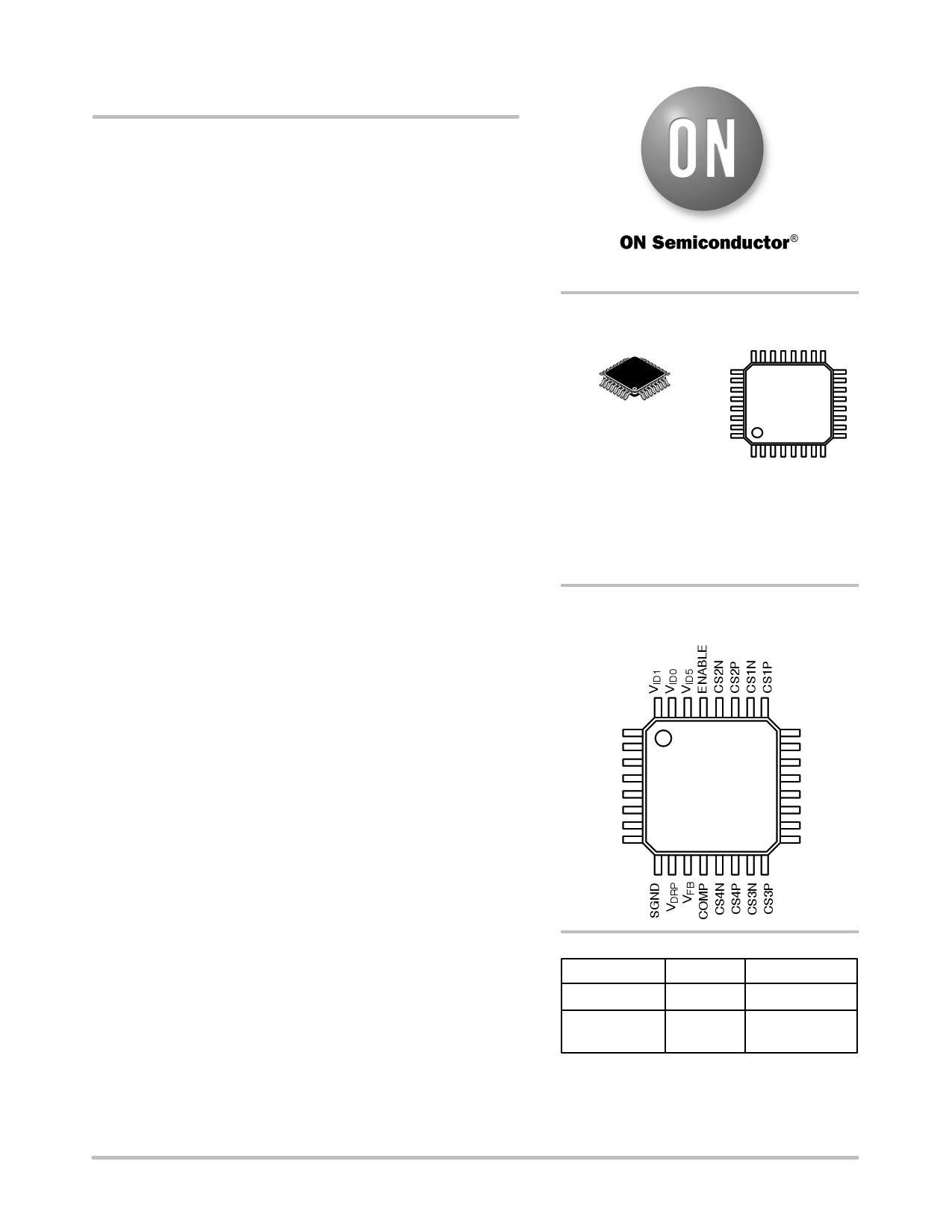
NCP5318
Two/Three/Four−Phase
Buck CPU Controller
The NCP5318 provides full−featured and flexible control
conforming to the Intel® VRM 10.1 specification for
high−performance CPUs. The IC can be programmed as a two−,
three− or four−phase buck controller, and the per−phase switching
frequency can be as high as 1.0 MHz. Combined with external gate
drivers and power components, the controller implements a compact,
highly integrated multi−phase buck converter.
Enhanced V2™ control inherently compensates for variations in
both line and load, and achieves current sharing between phases. This
control scheme provides fast transient response, reducing the need for
large banks of output capacitors and higher switching frequency.
Features
• Switching Regulator Controller
♦ Programmable 2/3/4 Phase Operation
♦ Lossless Current Sensing
♦ Enhanced V2 Control Method Provides Fast Transient Response
♦ Programmable Up to 1.0 MHz Switching Frequency Per Phase
♦ Programmable Adaptive Voltage Positioning
♦ Programmable Soft−Start Time
• Current Sharing
♦ Differential Current Sense Pins for Each Phase
♦ Current Sharing Within 10% Between Phases
• Protection Features
♦ Programmable Latching Overcurrent Protection
♦ “111110” and “111111” DAC Code Fault
♦ Latched Overvoltage Protection
♦ Undervoltage Lockout
♦ External Enable Control
♦ Three−State MOSFET Driver Control through DRVON Signal
• System Power Management
♦ 6−Bit DAC with 0.5% Tolerance Compatible with VRM 10.1
Specification
♦ Programmable Lower Power Good Threshold
♦ Power Good Output with Delay
♦ Pre−set No Load Offset Voltage
• Pb−Free Package is Available*
*For additional information on our Pb−Free strategy and soldering details, please
download the ON Semiconductor Soldering and Mounting Techniques
Reference Manual, SOLDERRM/D.
http://onsemi.com
MARKING
DIAGRAM
LQFP−32
FT SUFFIX
CASE 873A
NCP5318
AWLYYWWG
A = Assembly Location
WL = Wafer Lot
YY = Year
WW = Work Week
G = Pb−Free Package
PIN CONNECTIONS
(Top View)
VID2
VID3
VID4
PWRLS
VFFB
SS
PWRGD
DRVON
ILIM
ROSC
VCC
GATE1
GATE2
GATE3
GATE4
GND
ORDERING INFORMATION
Device
Package
Shipping†
NCP5318FTR2 LQFP−32 2000 Tape & Reel
NCP5318FTR2G LQFP−32 2000 Tape & Reel
(Pb−Free)
†For information on tape and reel specifications,
including part orientation and tape sizes, please
refer to our Tape and Reel Packaging Specification
Brochure, BRD8011/D.
© Semiconductor Components Industries, LLC, 2006
June, 2006 − Rev. 4
1
Publication Order Number
NCP5318/D
1 page 
NCP5318
ELECTRICAL CHARACTERISTICS (0°C < TA < 70°C; VCC = 12 V; CGATEx = 100 pF, CCOMP = 0.01 mF,
CSS = 0.1 mF, CVCC = 0.1 mF, RROSC = 95.3 kW, V(ILIM) = 1.0 V, DAC Code 010100; unless otherwise noted)
VOLTAGE IDENTIFICATION (VID) (continued)
VID4
1
Voltage Identification Bits
(Connect VFB to COMP, measure COMP)
VID3
VID2
VID1
VID0
1000
VID5
1
Nominal
Voltage
(V)
1.2500
Min
−0.5%
1.2248
Typ
No Load
1.2310
1
1
0
0
0
0
1.2625
1.2373
1.2435
1
0
1
1
1
1
1.2750
1.2497
1.2560
1
0
1
1
1
0
1.2875
1.2622
1.2685
1
0
1
1
0
1
1.3000
1.2746
1.2810
1
0
1
1
0
0
1.3125
1.2870
1.2935
1
0
1
0
1
1
1.3250
1.2995
1.3060
1
0
1
0
1
0
1.3375
1.3119
1.3185
1
0
1
0
0
1
1.3500
1.3243
1.3310
1
0
1
0
0
0
1.3625
1.3368
1.3435
1
0
0
1
1
1
1.3750
1.3492
1.3560
1
0
0
1
1
0
1.3875
1.3617
1.3685
1
0
0
1
0
1
1.4000
1.3741
1.3810
1
0
0
1
0
0
1.4125
1.3865
1.3935
1
0
0
0
1
1
1.4250
1.3990
1.4060
1
0
0
0
1
0
1.4375
1.4114
1.4185
1
0
0
0
0
1
1.4500
1.4238
1.4310
1
0
0
0
0
0
1.4625
1.4363
1.4435
0
1
1
1
1
1
1.4750
1.4487
1.4560
0
1
1
1
1
0
1.4875
1.4612
1.4685
0
1
1
1
0
1
1.5000
1.4736
1.4810
0
1
1
1
0
0
1.5125
1.4860
1.4935
0
1
1
0
1
1
1.5250
1.4985
1.5060
0
1
1
0
1
0
1.5375
1.5109
1.5185
0
1
1
0
0
1
1.5500
1.5233
1.5310
0
1
1
0
0
0
1.5625
1.5358
1.5435
0
1
0
1
1
1
1.5750
1.5482
1.5560
0
1
0
1
1
0
1.5875
1.5607
1.5685
0
1
0
1
0
1
1.6000
1.5731
1.5810
*VID Code is for reference only.
†VOUT No Load is the input to the error amplifier.
Max
+0.5%
1.2372
1.2497
1.2623
1.2748
1.2874
1.3000
1.3125
1.3251
1.3377
1.3502
1.3628
1.3753
1.3879
1.4005
1.4130
1.4256
1.4382
1.4507
1.4633
1.4758
1.4884
1.5010
1.5135
1.5261
1.5387
1.5512
1.5638
1.5763
1.5889
Units
V
V
V
V
V
V
V
V
V
V
V
V
V
V
V
V
V
V
V
V
V
V
V
V
V
V
V
V
V
http://onsemi.com
5
5 Page 
249
248
247
246
245
244
243
242
241
0
NCP5318
319
318
3 Phase Mode
317
316
4 Phase Mode
315
314
313
312
311
20 40 60 80 100 120
TEMPERATURE (°C)
Figure 8. Switching Frequency versus
Temperature (ROSC = 95.3 kW)
1.019
1.018
1.017
1.016
1.015
0
20 40 60 80 100 120
TEMPERATURE (°C)
Figure 9. VROSC versus Temperature
46
45
44
43
42
41
40
0 20 40 60 80 100 120
TEMPERATURE (°C)
Figure 11. Soft−start Charge Current versus
Temperature
4.75
4.70
4.65
4.60
4.55
4.50
0
20 40 60 80 100 120
TEMPERATURE (°C)
Figure 10. Current Sense to VDRP Gain versus
Temperature
5.50
5.00
4.50
4.00
3.50
0
20 40 60 80 100 120
TEMPERATURE (°C)
Figure 12. Current Sense Amplifier to PWM
Gain versus Temperature
http://onsemi.com
11
11 Page | ||
| Páginas | Total 31 Páginas | |
| PDF Descargar | [ Datasheet NCP5318.PDF ] | |
Hoja de datos destacado
| Número de pieza | Descripción | Fabricantes |
| NCP5314 | Two/Three/Four-Phase Buck CPU Controller | ON Semiconductor |
| NCP5316 | Four/Five/Six-Phase Buck CPU Controller | ON Semiconductor |
| NCP5318 | Two/Three/Four-Phase Buck CPU Controller | ON Semiconductor |
| Número de pieza | Descripción | Fabricantes |
| SLA6805M | High Voltage 3 phase Motor Driver IC. |
Sanken |
| SDC1742 | 12- and 14-Bit Hybrid Synchro / Resolver-to-Digital Converters. |
Analog Devices |
|
DataSheet.es es una pagina web que funciona como un repositorio de manuales o hoja de datos de muchos de los productos más populares, |
| DataSheet.es | 2020 | Privacy Policy | Contacto | Buscar |