|
|
|
PDF XE24S100 Data sheet ( Hoja de datos )
| Número de pieza | XE24S100 | |
| Descripción | FHSS Transceiver | |
| Fabricantes | Xecom | |
| Logotipo | ||
Hay una vista previa y un enlace de descarga de XE24S100 (archivo pdf) en la parte inferior de esta página. Total 16 Páginas | ||
|
No Preview Available !
www.DataSheet4U.com
XE24S100
June 2006
Xecom XE24S100 the Smallest, Complete 2.4 GHZ FHSS Transceiver
Description
The Xecom XE24S100 is a miniature 2.4 GHz Spread
Spectrum transceiver. It includes all RF hardware and a
micro-controller to manage the communications link.
The micro-controller manages all communications task
including configuration, data packaging, and Frequency
Hopping. The result is a complete wireless data
communications solution.
The XE24S100 package is unique because of its size
(less than 1.4 square inches), its leadless surface-mount
design, and the availability of an on-board chip antenna.
No competitive products can offer a solution as flexible,
convenient, and easy to integrate,
There are two XE24S100 models; the XE24S100C with
the on-board chip antenna and the XE24S100D with
dipole antenna connector. The dipole antenna improves
range while the chip antenna lowers system cost and
simplifies integration. Development Kits are available
for each version. A pin-compatible, higherer power
variant is also available, the XE24St00, for applications
with longer range requirements.
Models
• XE24S100C: Includes on-board chip antenna
• XE24S100D: Includes Dipole Antenna connector
• XE24S100DK-C: XE24S100C Development Kit
• XE24S100DK-D: XE24S100D Development Kit
Features
• 1.55” x 0.9” x 0.12” Leadless Surface-Mount package
• Utilizes globally available 2.4 GHz ISM band
• Control and Configuration with AT commands.
• 254 unique node addresses plus 254 unique Group
IDs allow multiple large networks to coexist.
• Programmable Transmit Power Output, max. 100 mW
• Typical Receiver Sensitivity -87 dBm
• Typical Throughput rate 20,000 bps
• Obstructed signal range 150 feet (XE24S100D)
• Multiple Low Power Operating modes
• SensorOnAirTM (patent pending) allows direct
connection of sensors to the Smart Transceiver
• Count-OffTM (patent pending) allows the host node to
download the status of all nodes in under 10 seconds.
• FCC Part 15 Modular Certification
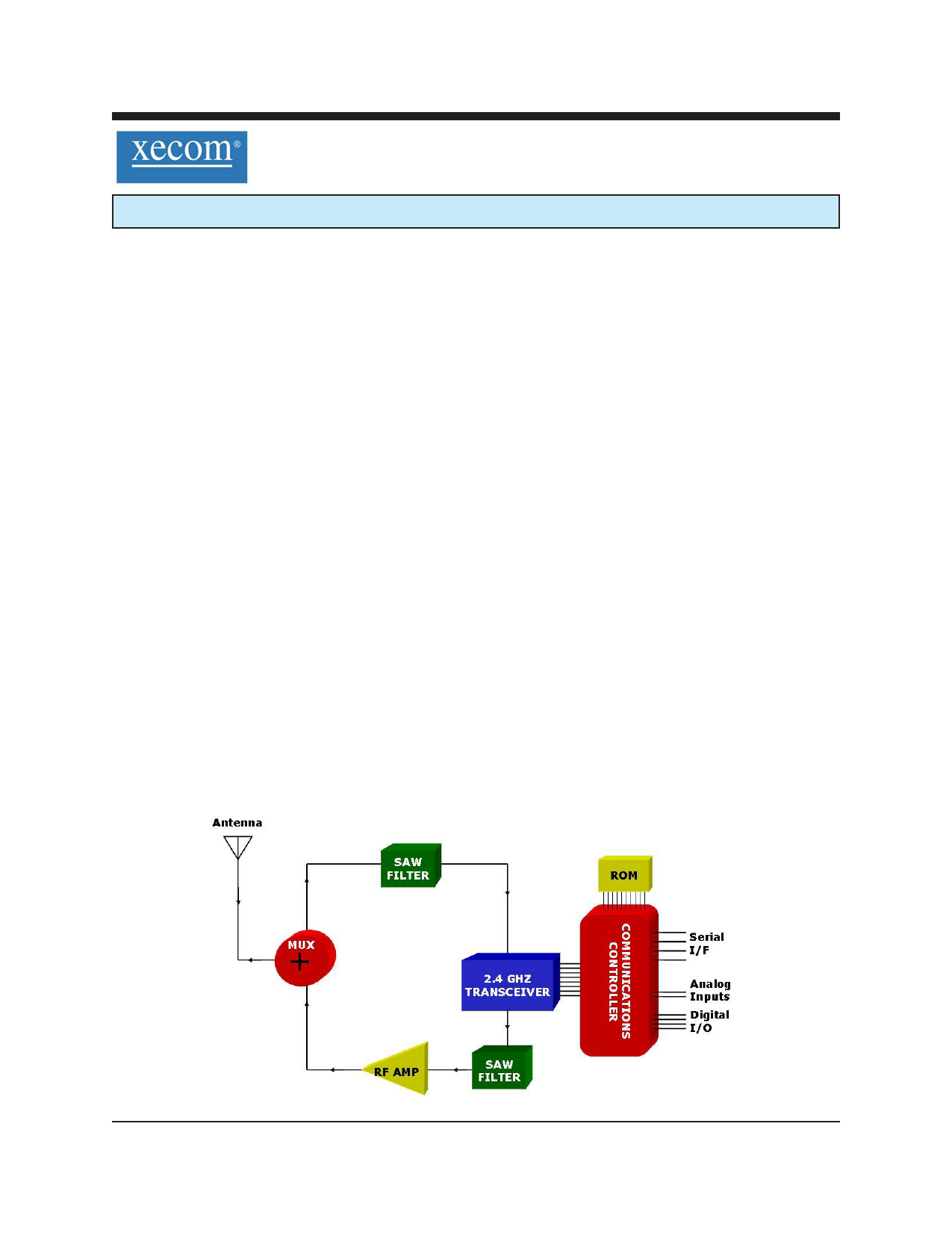
XE24S100 Block Diagram
XECOM
(1) XE24S100
1 page 
ABSOLUTE MAXIMUM RATINGS
VCC
Storage Temperature
Operating Temperature Range
3.6 Volts
-55O C to +125O C
-40O C to +85O C
WARNING: Exceeding any of these ratings will void the warranty and may damage the device
XE24S100 ELECTRICAL SPECIFICATIONS
Parameter
Min Typ Max Units Comments
VCC 3.0 3.3 3.6 Volts
ICC 200 mA Transmit (100 mW output)
30 mA Receive Mode
20 mA Idle Mode
1 10 mA RF Monitor
1.0 mA Power-Down Mode
0.050
mA Sleep Mode
Output Power:
4.5 100 mW 50 Ohm Load
Wireless Receive Sensitivity
-87 dBm
Range thru Physical Obstructions
150
feet 500 mW output
Frequency Hopping Channels
TBD
Frequency Band
2.400
2.4835 GHz
Antenna Output Impedance
50 Ohms
Latency
TBD mSec
Voh 2.4 Volts
Vol 0.8 Volts
Vih 2.0 Volts
Vil 0.4 Volts
XECOM
(5) XE24S100
5 Page 
AT COMMANDS
An asterisk indicates the factory default
A Answer Command - force response to a link
request
Dn Initiate a Wireless Link - attempt to
connect with the transceiver at address n.
En Echo Characters -
n=0 Characters not Echoed
n=1 Characters Echoed *
In Product Identification -
n=0 Display Product Code
n=1 Display Product Name
n=2 Display Model Number
n=3 Display Copyright
n=4 Display Firmware Revision
Qn Result Code Display -
n=0 Display Result Codes *
n=1 Do not Display Result Codes
Sn= Set Value of Register Sn
Sn? Read Value of Register Sn
Vn Response Type -
n=0 Numeric Responses
n=1 Full Word Responses *
Zn Reset - executes a soft Reset
n=0 Reset to Values in User Profile 0 *
n=1 Reset to Values in User Profile 1
&F Restore Factory Settings - return
commands and registers to default values.
&IAn? Read Local Analog Input “n” - allows
the host to read local analog inputs.
n=0 Read input ADC0
n=1 Read input ADC1
&IDn? Read Local Digital Input “n” - read the
status of the local digital inputs.
n=0 Read input DIO0
n=1 Read input DIO1
n=2 Read input DIO2
n=3 Read input DIO3
n=4 Read DIO4 (ADC0 set as digital I/O)
n=5 Read DIO5 (ADC1 set as digital I/O)
&IDn=z Set Local Digital Output “n” - sets
the state of the local digital outputs. z=0 sets
the output to a logic low; z=1 to a logic high.
n=0 Set output DIO0
n=1 Set output DIO1
n=2 Set output DIO2
n=3 Set output DIO3
&Kn Flow Control - selects the flow control used
between the system host and the XE24S100
n=0 Flow Control Disabled
n=3 RTS/CTS, hardware Flow Control
n=4 XON/XOFF, in-band Flow Control
&V View Active Configuration - sends the
active configuration data to the system host.
&Wn Store Current Configuration - loads the
current configuration into User Profile 0 or 1.
n=0 load configuration into User Profile 0
n=1 load configuration into User Profile 1
# B Wireless Broadcast - initiates wireless
broadcast for diagnostic purposes.
#C Count-Off Request (ASCII) - Initiates a
“Count-off’ sequence. Status report in ASCII.
#E: Count-Off Response (ASCII) - Programs
the 8 byte ASCII “Count-off” status message.
#E= Count-Off Response (Hex) - Programs the
8 byte “Count-off” response in hex format.
XECOM
(11) XE24S100
11 Page | ||
| Páginas | Total 16 Páginas | |
| PDF Descargar | [ Datasheet XE24S100.PDF ] | |
Hoja de datos destacado
| Número de pieza | Descripción | Fabricantes |
| XE24S100 | FHSS Transceiver | Xecom |
| Número de pieza | Descripción | Fabricantes |
| SLA6805M | High Voltage 3 phase Motor Driver IC. |
Sanken |
| SDC1742 | 12- and 14-Bit Hybrid Synchro / Resolver-to-Digital Converters. |
Analog Devices |
|
DataSheet.es es una pagina web que funciona como un repositorio de manuales o hoja de datos de muchos de los productos más populares, |
| DataSheet.es | 2020 | Privacy Policy | Contacto | Buscar |