|
|
|
PDF ZL38004 Data sheet ( Hoja de datos )
| Número de pieza | ZL38004 | |
| Descripción | Dedicated Voice Processor | |
| Fabricantes | Zarlink Semiconductor | |
| Logotipo | ||
Hay una vista previa y un enlace de descarga de ZL38004 (archivo pdf) en la parte inferior de esta página. Total 7 Páginas | ||
|
No Preview Available !
www.DataSheet4U.com
ZL38004
Dedicated Voice Processor
with Dual Channel Codec
Data Sheet
A full Design Manual is available to qualified
customers. To register, please send an email to
Features
• 100 MHz (200 MIPs) Zarlink voice processor with
Butterfly hardware accelerator and
breakpoint/interrupt controller
• On-board Data (26 Kbytes), Instruction (24
Kbytes RAM and Boot (3 Kbytes) ROM
• Dual ∆Σ ADCs with input buffer gain selection
programmable to either 8 or 16 kHz sampling
• Dual ∆Σ DACs with output sampling of 8, 16, 44.1
and 48 kHz and internal output driver
• 2048 tap Filter co-processor shared across up to
16 separate functions in 128 tap increments
• Dual function Inter-IC Sound (I2S) or Secondary
TDM port
June 2006
Ordering Information
ZL38004QCG1 100 Pin LQFP Trays, Bake &
Drypack
*Pb Free Matte Tin
-40°C to +85°C
• Primary PCM port supports TDM (ST BUS, GCI or
McBSP framing) or SSI modes at bit rates of 128,
256, 512, 1024, 2048, 4096, 8192 or 16384 Kb/sec
• Separate slave (microcontroller) and master
(Flash) SPI ports, maximum clock rate = 25 MHz
• Watchdog and 2 auxiliary timers
• 11 General Purpose Input/Output (GPIO) pins
• General purpose UART port
• Bootloadable for future Zarlink software upgrades
• External oscillator or crystal/ceramic resonator
• 1.2 V Core; 3.3 V IO with 5 V-tolerant inputs
• IEEE-1149.1 compatible JTAG port
Buffer
Driver
Buffer
CODEC[0]
ADC
DAC
IRQ
CODEC[1]
ADC
DAC
IRQ[15:0]
Interrupt
Controller
DSP
Core
Driver
IRQ
5
/ PCM P0
IRQ
ButterFly
Hardware
Accelerator
100 MHz MCLK
Instruction
RAM
APLL
OSC
24K
Bytes
3K Boot
Bytes ROM
Data RAM
27K
Bytes
PCM P0
Clock
Chain
JTAG
Timing
Generator
CODEC[1:0]
Device Clocks
IRQ
IRQ Master
SPI
IRQ Slave
SPI
IRQ
5
/
I2S
IRQ
IRQ APLL
Watchdog
IRQ
UART
IRQ
PCM P1
Filter
Co-processor
MCLK
AUX Timer1
AUX Timer2
IRQ
IRQ
GPIO
OSCo
OSCi
PCM_CLKi
PCM_LBCi
5
/
5
/
4
/
2
/
11
/
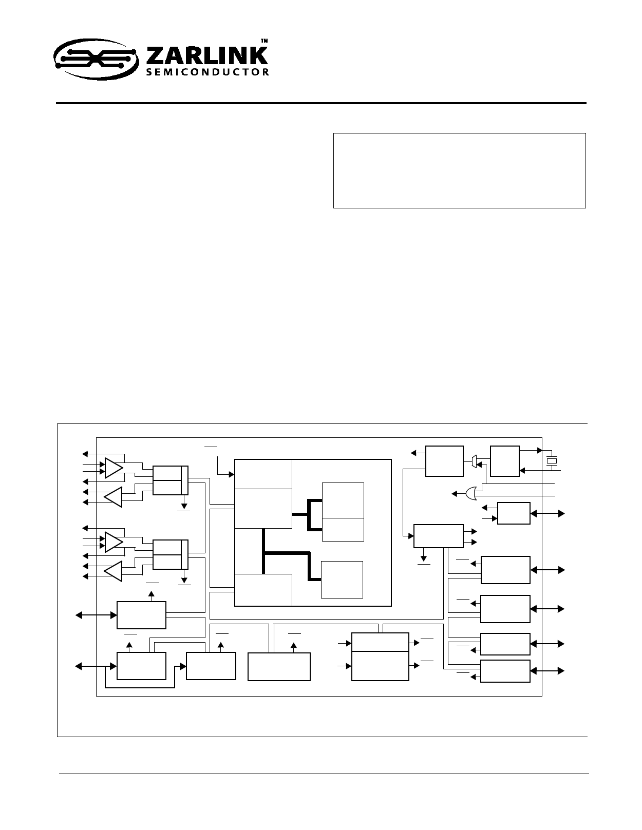
Figure 1 - Functional Block Diagram
3
Zarlink Semiconductor Inc.
Zarlink, ZL and the Zarlink Semiconductor logo are trademarks of Zarlink Semiconductor Inc.
Copyright 2006, Zarlink Semiconductor Inc. All Rights Reserved.
1 page 
ZL38004
Data Sheet
5.0 Host Microprocessor and Peripheral Interfaces
The ZL38004 provides 1 master SPI port (with 2 chip selects), 1 slave SPI ports and an UART. The master SPI
port’s primary function is to access and external FLASH memory to download firmware to the ZL38004.
The control/status registers and memory of the ZL38004 can be accessed (R/W) by an external host through the
Slave SPI and the UART ports. Register/Memory read and write accesses are carried out through a series of port
read and write accesses as follows:
5.1 Master SPI (FLASH Port)
The Master SPI port is used by the ZL38004 to access one or two peripheral devices (chip select signals
SPIM_CS[1:0]). It supports both SPI and MICROWIRE modes of operation and can write up to 40 bits or read up to
32 bits in a single access. The Chip Select output signals may be programmed for a single access or burst access.
All communication is MSB first and all pins of the master SPI port are outputs controlled by the ZL38004, except
SPIM_MISO.
5.2 Slave SPI (Host Port)
The slave SPI port may be used by an external host microprocessor to access (Read/Write) the ZL38004 internal
control/status registers and memory. Access is initiated when the external host makes signal SPIS_CS low and is
ended when this signal goes high. The host will then apply a clock (maximum 25 MHz) to signal SPIS_CLK to clock
data out of SPIS_MISO and in on SPIS_MOSI.
5.3 UART
The UART (Universal Asynchronous Receiver Transmitter) port may be used by an external host microprocessor to
access (Read/Write) the ZL38004 internal control/status registers and memory. The ZL38004 DSP will set up the
initial parameters of this port (i.e., master/slave, baud rate, stop bits, parity bit...) during the Boot process. After the
device has been booted these port options can be changed as per the firmware manual.
The UART port will support 8-bit data only with any combination of 1 start bit, 0 or 1 parity bit(s) and 1, 1.5 or 2 stop
bit(s).
The ZL38004 has 11 GPIO (General Purpose Input/Output) pins that can be individually configured as either input
or output. These pins are intended for low frequency signalling.
When a GPIO pin is defined as an input the state of that input pin is sampled with the internal master clock (Mclk =
100 MHz) and latched into the GPIO Read Register. This sampling can be stopped (Freeze) on an individual GPIO
pin. Individual pins of GPIO[4:0] may have an internal pull-down resistor activated/deactivated and individual pins of
GPIO[10:5] may have an internal pull-up activated/deactivated.
Immediately after a power-on reset (RST pin) the GPIO pins are defined as inputs and their state is captured in the
GPIO Start-Up Status Register. The state of this register is used by the Boot program to determine the base
functionality and programming options of the device.
Individual GPIO pins may also be defined as outputs with associated enable/disable (active/high impedance)
control.
7
Zarlink Semiconductor Inc.
5 Page | ||
| Páginas | Total 7 Páginas | |
| PDF Descargar | [ Datasheet ZL38004.PDF ] | |
Hoja de datos destacado
| Número de pieza | Descripción | Fabricantes |
| ZL38001 | Low-Voltage Acoustic Echo Canceller with Low ERL Compensation | Zarlink Semiconductor Inc |
| ZL38002 | Digital Echo Canceller | Zarlink Semiconductor |
| ZL38003 | AEC | Zarlink Semiconductor |
| ZL38004 | Dedicated Voice Processor | Zarlink Semiconductor |
| Número de pieza | Descripción | Fabricantes |
| SLA6805M | High Voltage 3 phase Motor Driver IC. |
Sanken |
| SDC1742 | 12- and 14-Bit Hybrid Synchro / Resolver-to-Digital Converters. |
Analog Devices |
|
DataSheet.es es una pagina web que funciona como un repositorio de manuales o hoja de datos de muchos de los productos más populares, |
| DataSheet.es | 2020 | Privacy Policy | Contacto | Buscar |