|
|
|
PDF MAX13342E Data sheet ( Hoja de datos )
| Número de pieza | MAX13342E | |
| Descripción | (MAX13342E / MAX13345E) 3-Wire Interface Full Speed USB Transceivers | |
| Fabricantes | Maxim Integrated Products | |
| Logotipo | ||
Hay una vista previa y un enlace de descarga de MAX13342E (archivo pdf) en la parte inferior de esta página. Total 18 Páginas | ||
|
No Preview Available !
www.DataSheet4U.com
19-0621; Rev 0; 10/06
3-Wire Interface Full-Speed USB Transceivers
With/Without Internal Series Resistors
General Description
The MAX13342E/MAX13345E USB-compliant trans-
ceivers are designed to minimize the area and external
components required to interface low-voltage ASICs to
USB. The devices comply with USB 2.0 specification for
full-speed-only (12Mbps) operation. The transceivers
include an internal 3.3V regulator, an internal 1.5kΩ D+
pullup resistor, and built-in ±15kV ESD protection cir-
cuitry to protect the USB I/0 ports (D+,D-). The
MAX13345E also has internal series resistors, allowing
it to be wired directly to a USB connector.
These devices operate with logic-supply voltages as
low as +2.3V, ensuring compatibility with low-voltage
ASICs. A low-power mode reduces current consump-
tion to less than 45µA. An enumerate function controls
the D+ pullup resistor, allowing devices to logically dis-
connect while remaining plugged in.
The MAX13342E has controlled output impedance of
2Ω (max) on D+/D-, allowing the use of external switch-
es to multiplex two different USB devices onto a single
USB connector. The MAX13345E has 43.5Ω (max)
internal resistors on D+/D- for direct connection to the
USB connector.
The MAX13342E/MAX13345E are equipped with DAT
and SE0 interface signals. These transceivers provide a
USB detection function that monitors the presence of
USB VBUS and signals the event.
These devices operate over the extended -40°C to +85°C
temperature range and are available in UCSP™ 2.0mm x
1.5mm and 14-pin TDFN (3mm x 3mm) packages.
UCSP™ is a trademark of Maxim Integrated Products, Inc.
Applications
PDAs
PC Peripherals
Cellular Telephones
Data Cradles
MP3 Players
Pin Configurations and Selector Guide appear at end of data
sheet.
Features
o USB 2.0 (Full-Speed, 12Mbps)-Compliant
Transceiver
o Internal Pullup
o VBUS Detection
o Internal Series Resistors (MAX13345E)
o ±15kV (HBM) ESD Protection on D+, D-, and VBUS
o Enumeration Input Controls D+ Pullup Resistor
o Supports 3-Wire DAT/SE0 Interface
o +2.3V to +3.6V Interface Voltage (VL)
o No Power-Supply Sequencing Required
o Low USB Output Impedance (MAX13342E)
Ordering Information
PART
PIN-
PACKAGE
TOP
MARK
PKG CODE
MAX13342EETD+
MAX13342EEBC+*
MAX13345EETD+
MAX13345EEBC+*
14 TDFN-EP
(3mm x 3mm)
12 UCSP
(2.0mm x 1.5mm)
14 TDFN-EP
(3mm x 3mm)
12 UCSP
(2.0mm x 1.5mm)
ACZ
ACU
ADA
ACX
T1433-2
B12-3
T1433-2
B12-3
*Future product—contact factory for availability.
+Denotes lead-free package.
EP = Exposed pad.
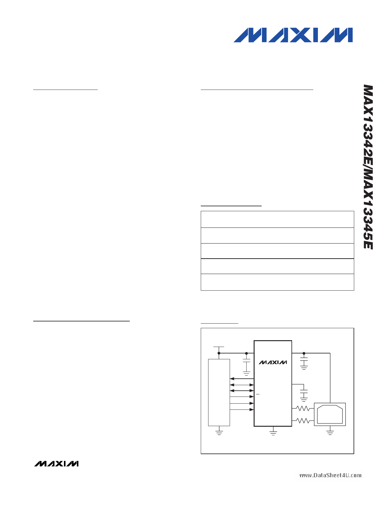
Typical Operating Circuits
SYSTEM
VOLTAGE
SUPPLY
0.1µF
SYSTEM
INTERFACE
VL VBUS
MAX13342E
BD
DAT
SEO
OE
ENUM
SUS
VTRM
D+
GND D-
1µF
1µF
31.6Ω
31.6Ω
USB
CONNECTOR
Typical Operating Circuits continued at end of data sheet.
________________________________________________________________ Maxim Integrated Products 1
For pricing, delivery, and ordering information, please contact Maxim/Dallas Direct! at
1-888-629-4642, or visit Maxim’s website at www.maxim-ic.com.
1 page 
www.DataSheet4U.com
3-Wire Interface Full-Speed USB Transceivers
With/Without Internal Series Resistors
(VBUS = +5V, VL = +3.3V, TA = +25°C, unless otherwise noted.)
Typical Operating Characteristics
DIFFERENTIAL RECEIVER PROPAGATION
DELAY vs. VL
20
18
TA = +85°C
16 TA = +25°C
14
12
10
8 TA = -40°C
6
4
1.2 1.5 1.8 2.1 2.4 2.7 3.0 3.3 3.6
VL (V)
SINGLE-ENDED RECEIVER PROPAGATION
DELAY vs. VBUS
20
OE = SUS = HIGH
18
16
TA = +85°C
14
12
10
8 TA = +25°C TA = -40°C
6
4
2
0
4.0 4.3 4.6 4.9 5.2 5.5
VBUS (V)
VL SUPPLY CURRENT
vs. D+/D- CAPACITANCE
26
24
22
20
18
16
14
12
10
8
0 22 44 66 88 110 132 154 176 198 220
CAPACITANCE (pF)
DIFFERENTIAL RECEIVER PROPAGATION
DELAY vs. VBUS
20
18 TA = +85°C
16 TA = +25°C
14
12
10
8 TA = -40°C
6
4
2
0
4.0 4.3 4.6 4.9 5.2 5.5
VBUS (V)
1.0
0.9
0.8
0.7
0.6
0.5
0.4
0.3
0.2
0.1
0
-40
TRANSMITTER SKEW
vs. TEMPERATURE
-15 10 35 60
TEMPERATURE (°C)
85
VBUS SUPPLY CURRENT
vs. D+/D- CAPACITANCE
1.7
1.6
1.5 VL = 2.5V
1.4
1.3
1.2
1.1
1.0
0 22 44 66 88 110 132 154 176 198 220
CAPACITANCE (pF)
SINGLE-ENDED RECEIVER PROPAGATION
DELAY vs. VL
30
OE = SUS = HIGH
28
26
24
22
20
18 TA = +25°C
TA = +85°C
16
14
12 TA = -40°C
10
1.2 1.5 1.8 2.1 2.4 2.7 3.0 3.3 3.6
VL (V)
1.5
1.4
1.3
1.2
1.1
1.0
0.9
0.8
0.7
0.6
-40
RECEIVER SKEW
vs. TEMPERATURE
-15 10 35 60
TEMPERATURE (°C)
85
40
38
36
34
32
30
28
26
24
22
20
4.0
VBUS SUSPEND CURRENT
vs. VBUS SUPPLY VOLTAGE
TA = +25°C
TA = +85°C
TA = -40°C
4.3 4.6 4.9 5.2 5.5
VBUS (V)
_______________________________________________________________________________________ 5
5 Page 
www.DataSheet4U.com
3-Wire Interface Full-Speed USB Transceivers
With/Without Internal Series Resistors
Table 3. Transmit Truth Table
(OE = 0, SUS = 0)
INPUTS
OUTPUTS
DAT
SE0
D+
D-
0001
0100
1010
1100
Applications Information
USB Data Transfer
Transmitting Data
The MAX13342E/MAX13345E transmit USB data to the
USB differentially on D+ and D- when OE is low. The
D+ and D- outputs are determined by SE0 and DAT
(see Table 3).
Receiving Data
Drive OE high and SUS low to receive data on D+/D-.
Differential data received on D+ and D- appear at DAT.
SE0 goes high only when both D+ and D- are low
(Table 4).
External Resistors
(MAX13342E)
The MAX13342E provides low internal resistance on
D+/D-. Two external series resistors for impedance
matching are required for USB. Place the resistors in
between the MAX13342E and the USB connector (see
Figure 2).
Table 4. Receive Truth Table
(OE = 1, SUS = 0)
INPUTS
OUTPUTS
D+
D-
DAT
SE0
0 0 *DAT 1
0 1 **0 0
1 0 **1 0
11X0
*Last state
**D+/D- differential receiver output
X = Undefined
External Capacitors
Use three external capacitors for proper operation.
Bypass VL to GND with a 0.1µF ceramic capacitor.
Bypass VBUS to GND with a 1µF ceramic capacitor.
Bypass VTRM to GND with a 1µF (min) ceramic or plas-
tic capacitor. Place all capacitors as close to the
device as possible.
UCSP Application Information
For the latest application details on UCSP construction,
dimensions, tape carrier information, printed circuit
board (PCB) techniques, bump-pad layout, and recom-
mended reflow temperature profile, as well as the latest
information on reliability testing results, refer to
Application Note 1891: UCSP—A Wafer-Level Chip-
Scale Package available on Maxim’s website at
www.maxim-ic.com/ucsp.
______________________________________________________________________________________ 11
11 Page | ||
| Páginas | Total 18 Páginas | |
| PDF Descargar | [ Datasheet MAX13342E.PDF ] | |
Hoja de datos destacado
| Número de pieza | Descripción | Fabricantes |
| MAX13342E | (MAX13342E / MAX13345E) 3-Wire Interface Full Speed USB Transceivers | Maxim Integrated Products |
| Número de pieza | Descripción | Fabricantes |
| SLA6805M | High Voltage 3 phase Motor Driver IC. |
Sanken |
| SDC1742 | 12- and 14-Bit Hybrid Synchro / Resolver-to-Digital Converters. |
Analog Devices |
|
DataSheet.es es una pagina web que funciona como un repositorio de manuales o hoja de datos de muchos de los productos más populares, |
| DataSheet.es | 2020 | Privacy Policy | Contacto | Buscar |