|
|
|
PDF AD7763 Data sheet ( Hoja de datos )
| Número de pieza | AD7763 | |
| Descripción | 24-Bit ADC | |
| Fabricantes | Analog Devices | |
| Logotipo | ||
Hay una vista previa y un enlace de descarga de AD7763 (archivo pdf) en la parte inferior de esta página. Total 30 Páginas | ||
|
No Preview Available !
Data Sheet
24-Bit, 625 kSPS, 109 dB Sigma-Delta
ADC with On-Chip Buffers, Serial Interface
AD7763
FEATURES
120 dB dynamic range at 78 kHz output data rate
109 dB dynamic range at 625 kHz output data rate
112 dB SNR at 78 kHz output data rate
107 dB SNR at 625 kHz output data rate
625 kHz maximum fully filtered output word rate
Programmable oversampling rate (32× to 256×)
Flexible serial interface
Fully differential modulator input
On-chip differential amplifier for signal buffering
Low-pass finite impulse response (FIR) filter with default
or user-programmable coefficients
Overrange alert bit
Digital offset and gain correction registers
Low power and power-down modes
Synchronization of multiple devices via SYNC pin
I2S interface mode
APPLICATIONS
Data acquisition systems
Vibration analysis
Instrumentation
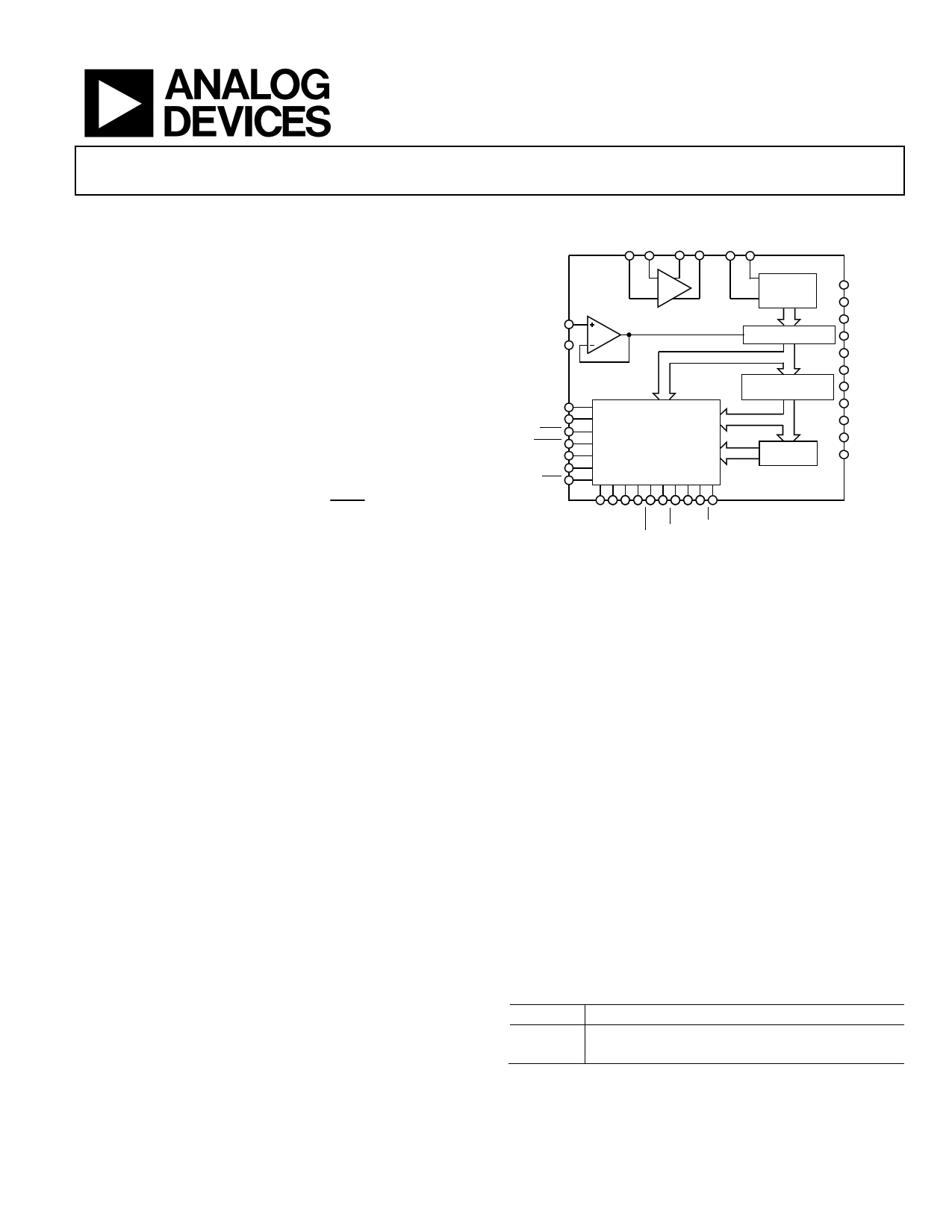
FUNCTIONAL BLOCK DIAGRAM
VIN– VIN+
DIFF
VREF+
REFGND
BUF
MCLK
MCLKGND
SYNC
RESET
SH2:0
ADR2:0
CDIV
AD7763
CONTROL LOGIC
I/O
OFFSET AND GAIN
REGISTERS
MULTIBIT
-
MODULATOR
RECONSTRUCTION
PROGRAMMABLE
DECIMATION
FIR FILTER
ENGINE
AVDD1
AVDD2
AVDD3
AVDD4
DECAPA
DECAPB
RBIAS
AGND
VDRIVE
DVDD
DGND
Figure 1.
GENERAL DESCRIPTION
The AD7763 high performance, 24-bit, Σ-Δ analog-to-digital
converter (ADC) combines wide input bandwidth and high
speed with the benefits of Σ-Δ conversion, as well as performance
of 107 dB SNR at 625 kSPS, making it ideal for high speed data
acquisition. A wide dynamic range, combined with significantly
reduced antialiasing requirements, simplifies the design process.
An integrated buffer to drive the reference, a differential ampli-
fier for signal buffering and level shifting, an overrange flag,
internal gain and offset registers, and a low-pass, digital FIR
filter make the AD7763 a compact, highly integrated data
acquisition device requiring minimal peripheral component
selection. In addition, the device offers programmable
decimation rates and a digital FIR filter, which can be user-
programmed to ensure that its characteristics are tailored for the
user’s application. The AD7763 is ideal for applications demanding
high SNR without necessitating the design of complex, front-
end signal processing.
The differential input is sampled at up to 40 MSPS by an analog
modulator. The modulator output is processed by a series of
low-pass filters, the final filter having default or user-programmable
coefficients. The sample rate, filter corner frequencies, and
output word rate are set by a combination of the external clock
frequency and the configuration registers of the AD7763.
The reference voltage supplied to the AD7763 determines the
analog input range. With a 4 V reference, the analog input range
is ±3.2 V differential-biased around a common mode of 2 V.
This common-mode biasing can be achieved using the on-chip
differential amplifiers, further reducing the external signal
conditioning requirements.
The AD7763 is available in an exposed paddle, 64-lead TQFP_EP
and is specified over the industrial temperature range from
−40°C to +85°C.
Table 1. Related Devices
Part No. Description
AD7760 24-bit, 2.5 MSPS, 100 dB Σ-Δ, parallel interface
AD7762 24-bit, 625 kSPS, 109 dB Σ-Δ, parallel interface
Rev. B
Document Feedback
Information furnished by Analog Devices is believed to be accurate and reliable. However, no
responsibility is assumed by Analog Devices for its use, nor for any infringements of patents or other
rights of third parties that may result from its use. Specifications subject to change without notice. No
license is granted by implication or otherwise under any patent or patent rights of Analog Devices.
Trademarksandregisteredtrademarksarethepropertyoftheirrespectiveowners.
One Technology Way, P.O. Box 9106, Norwood, MA 02062-9106, U.S.A.
Tel: 781.329.4700 ©2005–2014 Analog Devices, Inc. All rights reserved.
Technical Support
www.analog.com
1 page 
AD7763
Data Sheet
Parameter
REFERENCE INPUT
VREF Input Voltage
VREF Input DC Leakage Current
VREF Input Capacitance
POWER DISSIPATION
Total Power Dissipation
Standby Mode
POWER REQUIREMENTS
AVDD1 (Modulator Supply)
AVDD2 (General Supply)
AVDD3 (Differential Amplifier Supply)
AVDD4 (Reference Buffer Supply)
DVDD
VDRIVE
Normal Mode
AIDD1 (Modulator)
AIDD2 (General)
AIDD4 (Reference Buffer)
Low Power Mode
AIDD1 (Modulator)
AIDD2 (General)
AIDD4 (Reference Buffer)
AIDD3 (Diff Amp)
DIDD
DIGITAL I/O
MCLK Input Amplitude3
Input Capacitance
Input Leakage Current
Three-State Leakage Current (SDO)
VINH
VINL
VOH 4
VOL
Test Conditions/Comments
VDD3 = 3.3 V ± 5%
VDD3 = 5 V ± 5%
Normal power mode
Low power mode
Clock stopped
±5%
±5%
±5%
AVDD4 = 5 V
AVDD4 = 5 V
AVDD3 = 5 V, both modes
Both modes
Specification Unit
+2.5
+4.096
±1
5
V max
V max
µA max
pF max
955.5
651
6.35
mW max
mW max
mW typ
+2.5
+5
+3.15/+5.25
+3.15/+5.25
+2.5
+1.65/+2.7
V
V
V min/max
V min/max
V
V min/max
49/52
40/43
35/37
mA typ/max
mA typ/max
mA typ/max
26/28
20/23
10/11
41/45
56/62
mA typ/max
mA typ/max
mA typ/max
mA typ/max
mA typ/max
5
7.3
±1
±1
0.7 × VDRIVE
0.3 × VDRIVE
1.5
0.1
V typ
pF typ
μA/pin max
μA max
V min
V max
V min
V max
1 See the Terminology section.
2 SNR specifications in dB are referred to a full-scale input, FS, and tested with an input signal at 0.5 dB below full scale, unless otherwise specified.
3 While the AD7763 can function with an MCLK amplitude of less than 5 V, this is the recommended amplitude to achieve the performance as stated.
4 Tested with a 400 μA load current.
Rev. B | Page 4 of 32
5 Page 
AD7763
TERMINOLOGY
Signal-to-Noise Ratio (SNR)
The ratio of the rms value of the actual input signal to the rms
sum of all other spectral components below the Nyquist fre-
quency, excluding harmonics and dc. The value for SNR is
expressed in decibels.
Total Harmonic Distortion (THD)
The ratio of the rms sum of harmonics to the fundamental. For
the AD7763, it is defined as
THD(dB) = 20 log
V22 + V32 + V42 + V52 + V62
V1
where:
V1 is the rms amplitude of the fundamental.
V2, V3, V4, V5, and V6 are the rms amplitudes of the second
to the sixth harmonic.
Nonharmonic Spurious-Free Dynamic Range (SFDR)
The ratio of the rms signal amplitude to the rms value of the
peak spurious spectral component, excluding harmonics.
Dynamic Range
The ratio of the rms value of the full scale to the rms noise
measured with the inputs shorted together. The value for
dynamic range is expressed in decibels.
Data Sheet
Integral Nonlinearity (INL)
The maximum deviation from a straight line passing through
the endpoints of the ADC transfer function.
Differential Nonlinearity (DNL)
The difference between the measured and the ideal 1 LSB
change between any two adjacent codes in the ADC.
Zero Error
The difference between the ideal midscale input voltage (0 V)
and the actual voltage producing the midscale output code.
Zero Error Drift
The change in the actual zero error value due to a temperature
change of 1°C. It is expressed as a percentage of full scale at room
temperature.
Gain Error
The first transition (from 100…000 to 100…001) should occur
for an analog voltage 1/2 LSB above the nominal negative full
scale. The last transition (from 011…110 to 011…111) should
occur for an analog voltage 1 1/2 LSB below the nominal full
scale. The gain error is the deviation of the difference between
the actual level of the last transition and the actual level of the
first transition, from the difference between the ideal levels.
Gain Error Drift
The change in the actual gain error value due to a temperature
change of 1°C. It is expressed as a percentage of full scale at
room temperature.
Rev. B | Page 10 of 32
11 Page | ||
| Páginas | Total 30 Páginas | |
| PDF Descargar | [ Datasheet AD7763.PDF ] | |
Hoja de datos destacado
| Número de pieza | Descripción | Fabricantes |
| AD776 | 16-Bit 100 kSPS Oversampling ADC | Analog Devices |
| AD7760 | 2.5 MSPS 20-Bit ADC | Analog Devices |
| AD7761 | Simultaneous Sampling ADC | Analog Devices |
| AD7762 | With On-Chip Buffer 625 KSPS | Analog Devices |
| Número de pieza | Descripción | Fabricantes |
| SLA6805M | High Voltage 3 phase Motor Driver IC. |
Sanken |
| SDC1742 | 12- and 14-Bit Hybrid Synchro / Resolver-to-Digital Converters. |
Analog Devices |
|
DataSheet.es es una pagina web que funciona como un repositorio de manuales o hoja de datos de muchos de los productos más populares, |
| DataSheet.es | 2020 | Privacy Policy | Contacto | Buscar |