|
|
|
PDF DS1856 Data sheet ( Hoja de datos )
| Número de pieza | DS1856 | |
| Descripción | Temperature-Controlled Resistors | |
| Fabricantes | Maxim Integrated Products | |
| Logotipo | ||
Hay una vista previa y un enlace de descarga de DS1856 (archivo pdf) en la parte inferior de esta página. Total 30 Páginas | ||
|
No Preview Available !
www.DataSheet4U.com
Rev 1; 4/05
Dual, Temperature-Controlled Resistors with Inter-
nally Calibrated Monitors and Password Protection
General Description
The DS1856 dual, temperature-controlled, nonvolatile
(NV) variable resistors with three monitors consists of
two 256-position, linear, variable resistors; three analog
monitor inputs (MON1, MON2, MON3); and a direct-to-
digital temperature sensor. The device provides an
ideal method for setting and temperature-compensating
bias voltages and currents in control applications using
minimal circuitry. The variable resistor settings are
stored in EEPROM memory and can be accessed over
the 2-wire serial bus.
Relative to other members of the family, the DS1856 is
essentially a DS1859 with a DS1852-friendly memory
map. In particular, the DS1856 can be configured so
the 128 bytes of internal Auxiliary EEPROM memory is
mapped into Main Device Table 00h and Table 01h,
maintaining compatibility between both the
DS1858/DS1859 and the DS1852. The DS1856 also
features password protection equivalent to the DS1852,
further enhancing compatibility between the two.
Applications
Optical Transceivers
Optical Transponders
Instrumentation and Industrial Controls
RF Power Amps
Diagnostic Monitoring
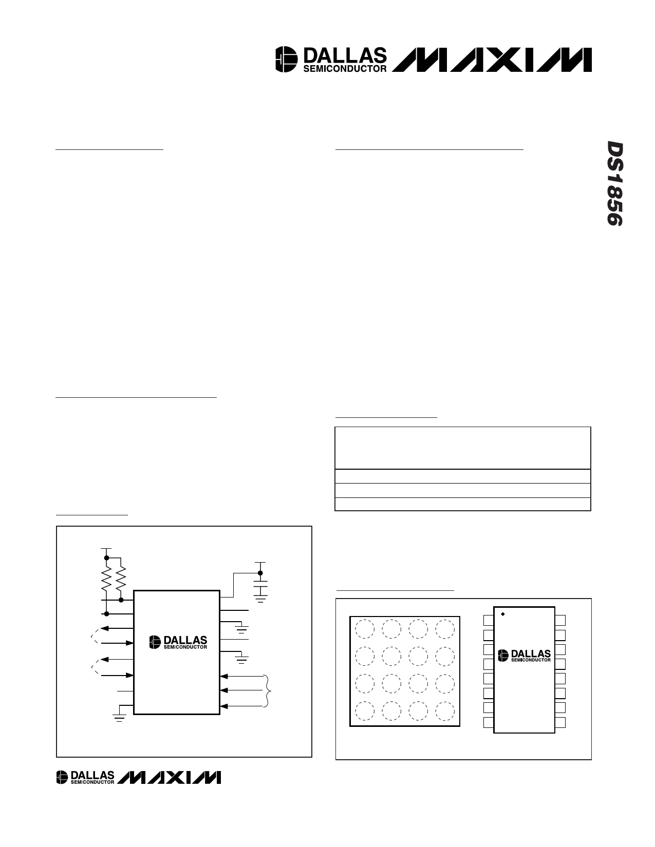
Typical Operating Circuit
VCC
VCC = 3.3V
4.7kΩ
2-WIRE
INTERFACE
Tx-FAULT
LOS
4.7kΩ
1
SDA
2
SCL
3
OUT1
4
IN1
5
OUT2
6
IN2
7
N.C.
8
GND
DS1856
16
VCC
15
H1
14
L1
13
H0
12
L0
0.1µF
DECOUPLING
CAPACITOR
TO LASER BIAS
CONTROL
TO LASER
MODULATION
CONTROL
11 Rx POWER*
MON3
10 Tx POWER*
MON2
MON1 9 Tx BIAS*
DIAGNOSTIC
INPUTS
*SATISFIES SFF-8472 COMPATIBILITY
Features
♦ SFF-8472 Compatible
♦ Five Monitored Channels (Temperature, VCC,
MON1, MON2, MON3)
♦ Three External Analog Inputs (MON1, MON2, MON3)
That Support Internal and External Calibration
♦ Scalable Dynamic Range for External Analog Inputs
♦ Internal Direct-to-Digital Temperature Sensor
♦ Alarm and Warning Flags for All Monitored
Channels
♦ Two Linear, 256-Position, Nonvolatile Temperature-
Controlled Variable Resistors
♦ Resistor Settings Changeable Every 2°C
♦ Three Levels of Security
♦ Access to Monitoring and ID Information
Configurable with Separate Device Addresses
♦ 2-Wire Serial Interface
♦ Two Buffers with TTL/CMOS-Compatible Inputs and
Open-Drain Outputs
♦ Operates from a 3.3V or 5V Supply
♦ -40°C to +95°C Operating Temperature Range
Ordering Information
PART
RES0/RES1
RESISTANCE
(kΩ)
PIN-PACKAGE
DS1856E-050
50/50
16 TSSOP
DS1856E-050/T&R
50/50
16 TSSOP
DS1856B-050
50/50
16-Ball CSBGA
Ordering Information continued at end of data sheet.
+Denotes lead free.
*Future product—contact factory for availability.
T&R denotes tape-and-reel.
All parts operate at the -40°C to +95°C temperature range.
Pin Configurations
TOP VIEW
A IN1
SCL VCC
H1
B OUT2 SDA
H0
L1
C N.C. IN2 OUT1 MON3
D GND L0 MON1 MON2
1234
CSBGA (4mm x 4mm)
1.0mm PITCH
SDA 1
SCL 2
OUT1 3
IN1 4
OUT2 5
IN2 6
N.C. 7
GND 8
DS1856
TSSOP
16 VCC
15 H1
14 L1
13 H0
12 L0
11 MON3
10 MON2
9 MON1
______________________________________________ Maxim Integrated Products 1
For pricing delivery, and ordering information please contact Maxim/Dallas Direct! at
1-888-629-4642, or visit Maxim’s website at www.maxim-ic.com.
1 page 
www.DataSheet4U.com
Dual, Temperature-Controlled Resistors with Inter-
nally Calibrated Monitors and Password Protection
Note 10: After this period, the first clock pulse is generated.
Note 11: The maximum tHD:DAT only has to be met if the device does not stretch the LOW period (tLOW) of the SCL signal.
Note 12: A device must internally provide a hold time of at least 300ns for the SDA signal (see the VIH MIN of the SCL signal) to
bridge the undefined region of the falling edge of SCL.
Note 13: CB—total capacitance of one bus line, timing referenced to 0.9 x VCC and 0.1 x VCC.
Note 14: Guaranteed by design.
Typical Operating Characteristics
(VCC = 5.0V, TA = +25°C, for both 50kΩ and 20kΩ versions, unless otherwise noted.)
SUPPLY CURRENT vs. TEMPERATURE
800
SDA = SCL = VCC
750
700
650
600
-40 -20 0 20 40 60 80 100
TEMPERATURE (°C)
RESISTANCE vs. SETTING
20
20kΩ VERSION
15
10
5
0
0 50 100 150 200 250
SETTING (DEC)
SUPPLY CURRENT vs. VOLTAGE
800
SDA = SCL = VCC
750
700
650
600
550
500
450
400
3.0 3.5 4.0 4.5 5.0 5.5
VOLTAGE (V)
ACTIVE SUPPLY CURRENT
vs. SCL FREQUENCY
800
SDA = VCC
780
760
740
720
700
0
100 200 300
SCL FREQUENCY (kHz)
400
RESISTANCE vs. SETTING
60
50kΩ VERSION
50
40
30
20
10
0
0 50 100 150 200 250
SETTING (DEC)
RESISTOR 0 INL (LSB)
1.0
0.8
0.6
0.4
0.2
0
-0.2
-0.4
-0.6
-0.8
-1.0
0 25 50 75 100 125 150 175 200 225 250
SETTING (DEC)
_____________________________________________________________________ 5
5 Page 
www.DataSheet4U.com
Dual, Temperature-Controlled Resistors with Inter-
nally Calibrated Monitors and Password Protection
Table 4. ADEN Address Configuration
ADEN
(ADDRESS
ENABLE)
NO. OF SEPARATE
DEVICE
ADDRESSES
ADDITIONAL
INFORMATION
0 2 See Figure 2
1 1 (Main Device Only) See Figure 3
Table 5. ADEN and ADFIX Bits
ADEN
0
0
1
1
ADFIX
0
1
0
1
AUXILIARY
ADDRESS
A0h
A0h
—
—
MAIN ADDRESS
A2h
EEPROM
(Table 03, 8Ch)
A2h
EEPROM
(Table 03, 8Ch)
DEC HEX 2-WIRE ADDRRESS A0h
0 0 00h
AUXILIARY DEVICE
EEPROM
AUXILIARY MEMORY
(128 BYTES)
DEC HEX 2-WIRE ADDRESS A2h (DEFAULT)
00
00h
MAIN DEVICE
LOWER MEMORY
NOTE 1: ADEN BIT = 0. AUXILIARY MEMORY IS ADDRESSED USING THE AUXILIARY DEVICE
NOTE 1. 2-WIRE SLAVE ADDRESS OF A0h, AND THE REMAINDER OF THE MEMORY IS
NOTE 1. ADDRESSED USING THE MAIN DEVICE 2-WIRE SLAVE ADDRESS OF A2h
NOTE 1. (WHEN ADFIX = 0).
NOTE 2: TABLES 00h, 01h, AND 02h DO NOT EXIST.
127 7F
PASSWORD ENTRY
(PWE) (4 BYTES)
7Fh
127 7F
TABLE SELECT BYTE 7Fh
128 80
80h
TABLE 03h
80h
TABLE 04h
80h
TABLE 05h
183 B7
CONFIGURATION
TABLE
B7h
RESISTOR 0
LOOK-UP TABLE
(72 BYTES)
RESISTOR 1
LOOK-UP TABLE
(72 BYTES)
199 C7
200 C8
255 FF
C7h C7h
F0h
RESERVED AND
CALIBRATION
CONSTANTS
FFh
F0h
RESERVED AND
CALIBRATION
CONSTANTS
FFh
Figure 2. Memory Organization, ADEN = 0
Variable Resistors
The value of each variable resistor is determined by
a temperature-addressed look-up table, which can
assign a unique value (00h to FFh) to each resistor for
every 2°C increment over the -40°C to +102°C range
(see Table 3). See the Temperature Conversion section
for more information.
The variable resistors can also be used in manual
mode. If the TEN bit equals 0, the resistors are in man-
ual mode and the temperature indexing is disabled.
The user sets the resistors in manual mode by writing
to addresses 82h and 83h in Table 03 to control resis-
tors 0 and 1, respectively.
Memory Description
The memory of the DS1856 is divided into two areas
referred to as the Main Device and the Auxiliary
Device. The Main Device comprises all of the DS1856
specific memory while the Auxiliary Device consists of
128 bytes of general-purpose EEPROM and is espe-
cially useful in GBIC applications. Main and Auxiliary
____________________________________________________________________ 11
11 Page | ||
| Páginas | Total 30 Páginas | |
| PDF Descargar | [ Datasheet DS1856.PDF ] | |
Hoja de datos destacado
| Número de pieza | Descripción | Fabricantes |
| DS1851 | Dual Temperature-Controlled NV Digital-to-Analog Converters | Dallas Semiconducotr |
| DS1852 | Optical Transceiver Diagnostic Monitor | Dallas Semiconductor |
| DS1854 | Dual Temperature-Controlled Resistors | Maxim Integrated Products |
| DS1855B-010 | Dual Nonvolatile Digital Potentiometer and Secure Memory | Dallas Semiconducotr |
| Número de pieza | Descripción | Fabricantes |
| SLA6805M | High Voltage 3 phase Motor Driver IC. |
Sanken |
| SDC1742 | 12- and 14-Bit Hybrid Synchro / Resolver-to-Digital Converters. |
Analog Devices |
|
DataSheet.es es una pagina web que funciona como un repositorio de manuales o hoja de datos de muchos de los productos más populares, |
| DataSheet.es | 2020 | Privacy Policy | Contacto | Buscar |