|
|
|
PDF EDE300 Data sheet ( Hoja de datos )
| Número de pieza | EDE300 | |
| Descripción | Parallel / Serial Transceiver IC | |
| Fabricantes | E-LAB Digital Engineering | |
| Logotipo | ||
Hay una vista previa y un enlace de descarga de EDE300 (archivo pdf) en la parte inferior de esta página. Total 9 Páginas | ||
|
No Preview Available !
www.DataSheet4U.com
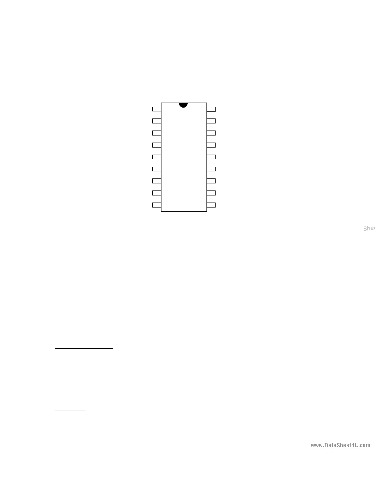
EDE300 Parallel/ Serial Transceiver IC
Data Direction, Output Latch 1
0=2400,1=9600 2
0=Local, 1=Host 3
Connect to +5V DC 4
Digital Ground 5
Data I/O Pin 0 6
Data I/O Pin 1 7
Data I/O Pin 2 8
Data I/O Pin 3 9
EDE300
Dir/Latch XMIT
BAUD
RCV
Mode
OSC1
+5V
OSC2
GND
+5V
D0 D7
D1 D6
D2 D5
D3 D4
18 Serial Transmit
17 Serial Receive
16 Oscillator Connection
15 Oscillator Connection
14 Connect to +5V DC
13 Data I/O Pin 7
12 Data I/O Pin 6
11 Data I/O Pin 5
10 Data I/O Pin 4
DataSheet4U.com
The EDE300 Parallel/ Serial Transceiver IC is a 5 volt, 18 pin package designed to
conveniently convert 8-bit parallel data into serial format and vice-versa. The EDE300 is ideal for
logging data to a PC, controlling hardware via the PC serial port, communicating 8-bit data via a
serial connection, and expanding I/O capabilities on microcontrollers and Stamps. The EDE300 is
BAUD-selectable, offering both 2400 and 9600 BAUD communication. PC connection requires the
use of a voltage level shifter such as the MAX233. The EDE300 can be configured as either a half-
duplex transmitter, a half-duplex receiver, or a half-duplex bi-directional transceiver.
PIN DEFINITIONS
Flow Control Pins:
Data Direction, /Latch (PIN 1):
Baud Rate (PIN 2):
Mode (PIN 3):
Data Pins:
Serial Transmit (PIN 18) :
Serial Receive (PIN 17):
D0..D7 (PIN 6..PIN 13):
In Local Control Mode pin is an INPUT:
Input of 0 = Parallel to Serial, 1 = Serial to Parallel.
In Host Control Mode, pin is an OUTPUT:
EDE300 drives this pin low on receive, high on transmit
0 = 2400 BAUD, (N 8 1); 1 = 9600 BAUD, (N 8 1)
0 = Local Control Mode, 1 = Host Control Mode
Serial data is output from the EDE300 via this pin
Serial data is input to the EDE300 via this pin
Data I/O Pins (DO is least significant bit)
DataSheet4U.com
DataSheet4 U .com
COPYRIGHT © 1996 E-Lab Digital Engineering, Inc. All Rights Reserved. Page # 1
DataSheet4U.com
DataShee
1 page 
www.DataSheet4U.com
Making use of the Dir/ Latch pin, the EDE300 can simultaneously latch data from a PC/ Stamp and
transmit data to the PC/ Stamp. The host PC/ Stamp would simply send a "1" command followed by
an output data byte, and then send a "2" command to tell the EDE300 to transmit data back. This
arrangement is shown in Figure Four below. The Dir/ Latch pin causes a data receive request to be
latched onto the '373, and a data transmit request to read from the '245. Note: use of the '245 may
in some circumstances cause brief glitches on the '373 outputs. We recommend this arrangement
only for output devices in which a small (0 to 25 ns) output glitch would be acceptable (eg. LED's,
relay control, etc.).
et4U.com
DataSheet4U.com
DataShee
Figure Four: Simultaneous Bi-directional Host-Control Mode Arrangement
The following code, written in 'Turbo C', illustrates one method for using the EDE300 in bi-
directional mode:
#include <stdio.h>
char value;
/* main loop data variable */
send (char x)
{
while ((inportb(0x3FD) & 0x20) == 0);
outportb(0x3F8,0x31);
while ((inportb(0x3FD) & 0x20) == 0);
outportb(0x3F8,x);
}
DataSheet4U.com
/* write 'x' to EDE300 */
/* hold until transmitter is ready */
/* select 'receive byte' on EDE300 */
/* hold until transmitter is ready */
/* write 'x' to EDE300 */
COPYRIGHT © 1996 E-Lab Digital Engineering, Inc. All Rights Reserved. Page # 5
DataSheet 4 U .com
DataSheet4U.com
5 Page | ||
| Páginas | Total 9 Páginas | |
| PDF Descargar | [ Datasheet EDE300.PDF ] | |
Hoja de datos destacado
| Número de pieza | Descripción | Fabricantes |
| EDE300 | Parallel / Serial Transceiver IC | E-LAB Digital Engineering |
| Número de pieza | Descripción | Fabricantes |
| SLA6805M | High Voltage 3 phase Motor Driver IC. |
Sanken |
| SDC1742 | 12- and 14-Bit Hybrid Synchro / Resolver-to-Digital Converters. |
Analog Devices |
|
DataSheet.es es una pagina web que funciona como un repositorio de manuales o hoja de datos de muchos de los productos más populares, |
| DataSheet.es | 2020 | Privacy Policy | Contacto | Buscar |