|
|
|
PDF UCB1500 Data sheet ( Hoja de datos )
| Número de pieza | UCB1500 | |
| Descripción | PCI to AC97 bridge/host controller | |
| Fabricantes | NXP Semiconductors | |
| Logotipo | ||
Hay una vista previa y un enlace de descarga de UCB1500 (archivo pdf) en la parte inferior de esta página. Total 30 Páginas | ||
|
No Preview Available !
( DataSheet : www.DataSheet4U.com )
UCB1500
PCI to AC97 bridge/host controller
Rev. 01 — 4 February 2000
Objective specification
1. General description
UCB1500 is a PCI-to-AC97 Bridge/Host Controller for modem or audio codecs
equipped with the AC-link interface. It integrates a PCI 2.2 compliant interface for
communication with the host PC, with built in support for PPMI (PCI Power
Management Interface) and wake-up. It also integrates an AC97 Rev. 2.1 compliant
host controller for connection to up to two AC-Link codecs, including analog modem
front ends such as the Philips UCB1510, and audio codecs.
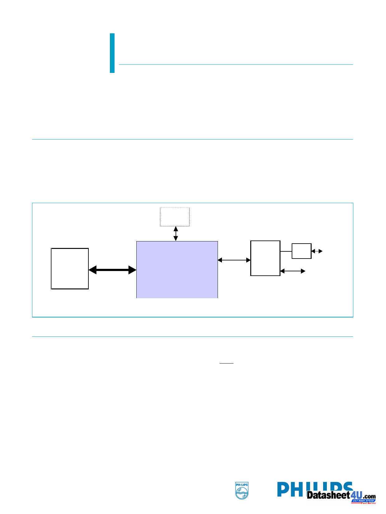
Optional
EEPROM
Host PC
PCI Interface
UCB1500
AC97
Interface
UCB1510
DAA
Phone
Line
GPIO
c
c
Fig 1. Application with Philips UCB1510 analog modem front end
2. Features
s 32-bit PCI 2.2 interface with bus master support
x Support up to two PCI functions with independent scatter/gather DMA
x PPMI and wake-up support via PME and VAUX
x Download of subsystem IDs and auxiliary power consumption via optional
serial EEPROM
x 5 V tolerant interface for motherboard/PC add-on
s AC97 rev 2.1 compliant host controller interface
x Supports up to two codecs
x Supports variable sample rate via the SLOTREQ protocol and valid tag bits
x Low latency GPIO data transfer
x Support modem wake-up on ring from D3cold
www.DataSheet4U.com
1 page 
Philips Semiconductors
UCB1500
PCI to AC97 bridge/host controller
7. PCI configuration space
7.1 Overview
By default, UCB1500 supports a single modem function. Under control of BIOS or an
external serial EEPROM, UCB1500 can support a maximum of two PCI functions,
which are typically one modem plus one audio functions. To allow IHV to overwrite
parameters such as Device ID, Vendor ID, Subsystem Vendor ID, Subsystem ID,
Class Code and Power Management Capabilities, UCB1500 provides two schemes:
• For each function, Device ID, Vendor ID, Subsystem Vendor ID, Subsystem ID,
Class Code and Power Management Capabilities are placed in a dedicated PCI
configuration read/write area accessible by the corresponding function. An enable
bit for Function 1 is placed in a dedicated read/write area accessible by Function 0.
This allows IHVs to enable Function 1 and change the corresponding read-only
parameters of Functions 0 and 1 (if enabled) in the BIOS POST routine when
UCB1500 is used as a motherboard device.
• In case UCB1500 is used as a PCI card which BIOS cannot control, the above
parameters, together with Function 1 enable, can be changed by the external
serial EEPROM.
The EEPROM data map is given in Table 3.
Table 3: EEPROM data map
Byte address Tag
00-01h
signature
02-03h
control
04-05h
06-07h
08-09h
0A-0Bh
0C-0Dh
0Eh
0F-11h
12-13h
14-15h
16-17h
18-19h
1A-1Bh
1Ch
1D-1Fh
sub_vendorID
subsystemID
pmc
vendorID
deviceID
--
classCode
sub_vendorID
subsystemID
pmc
vendorID
deviceID
--
classCode
Description
1516h = valid signature, otherwise disable autoloading.
Bit 0: 1=enable function 1, 0=disable function 1
Bit 1: 1=enable function 0 auto-loading from address 04-9Dh
Bit 2: 1=enable function 0 auto-loading from address 0A-11h
Bit 3: 1=enable function 1 auto-loading from address 10-17h
Bit 4: 1=enable function 1 auto-loading from address 18-1Fh
Other bits: reserved and must be 0s.
Function 0 subsystem vendor ID, PCI configuration space address 2C-2Dh.
Function 0 subsystem ID, PCI configuration space address 2E-2Fh.
Function 0 power management capabilities, PCI configuration space address 82h.
Function 0 vendor ID, PCI configuration space address 00-01h.
Function 0 device ID, PCI configuration space address 02-03h.
Reserved.
Function 0 Class Code, PCI configuration space address 09-0Bh.
Function 1 subsystem vendor ID, PCI configuration space address 2C-2Dh.
Function 1 subsystem ID, PCI configuration space address 2E-2Fh.
Function 1 power management capabilities, PCI configuration space offset 82h.
Function 1 vendor ID, PCI configuration space address 00-01h.
Function 1 device ID, PCI configuration space address 02-03h.
Reserved.
Function 1 Class Code, PCI configuration space address 09-0Bh.
9397 750 06854
Objective specification
Rev. 01 — 4 February 2000
© Philips Electronics N.V. 2000. All rights reserved.
5 of 58
5 Page 
Philips Semiconductors
UCB1500
PCI to AC97 bridge/host controller
[82]: Power Management Capabilities (read only)
Table 12: Power Management Capabilities register bit description
Read only
Bit Description
15-11(r) PME support
This 5-bit field indicates the power states in which the function may assert PME.
Value is set to 11001 b if VAUX_AV = 1 to indicate PME can be asserted from
D3cold and D0. If VAUX_AV = 0, this field is set to 01001b to indicate PME can be
asserted from D3hot and D0.
The entire setting can be overwritten by BIOS via writing to 6Ah, or an external
EEPROM. If VAUX_AV = 0, bit 15 shall always be zero. If VAUX = 1, bit 15 shall
reflect the setting of 6Ah, or that loaded from EEPROM.
10(r)
D2 support
This bit is set to ‘0’ to indicate that function does not support the D2 power
management state. This setting can be overwritten by BIOS via 6Ah, or with the
external EEPROM.
9(r) D1 support
This bit is set to ‘0’ to indicate that function does not support the D1 power
management state. This setting can be overwritten by BIOS via 6Ah, or with the
external EEPROM.
8-6(r)
Aux_Current
These bits are set to ‘0’ for PCI-PM 1.0 compliance. For PCI-PM 1.1 compliance,
these bits are overwritten by BIOS via 6Ah, or loaded from an external EEPROM
to reflect the 3.3VAUX current requirement.
5(r) DSI
The Device Specific Initialization bit indicates whether special initialization of this
function is required (beyond the standard PCI configuration header) before the
generic class device driver is able to use it. This register is set to ‘0’ to indicate
that it does not require special initialization.
4(r) Reserved.
3(r) PME Clock
This bit is a ‘0’, indicating that the function does not rely on the presence of the
PCI clock for PME operation.
2:0(r)
Version
This register is set to 001b, indicating that this function complies with Rev 1.0 of
the PCI Power Management Interface Specification. These bits can also be
overwritten by BIOS via 6Ah, or loaded from an external EEPROM to 010b for
compliance with PCI-PM 1.1.
9397 750 06854
Objective specification
Rev. 01 — 4 February 2000
© Philips Electronics N.V. 2000. All rights reserved.
11 of 58
11 Page | ||
| Páginas | Total 30 Páginas | |
| PDF Descargar | [ Datasheet UCB1500.PDF ] | |
Hoja de datos destacado
| Número de pieza | Descripción | Fabricantes |
| UCB1500 | PCI to AC97 bridge/host controller | NXP Semiconductors |
| Número de pieza | Descripción | Fabricantes |
| SLA6805M | High Voltage 3 phase Motor Driver IC. |
Sanken |
| SDC1742 | 12- and 14-Bit Hybrid Synchro / Resolver-to-Digital Converters. |
Analog Devices |
|
DataSheet.es es una pagina web que funciona como un repositorio de manuales o hoja de datos de muchos de los productos más populares, |
| DataSheet.es | 2020 | Privacy Policy | Contacto | Buscar |