|
|
|
PDF CAT24WC64 Data sheet ( Hoja de datos )
| Número de pieza | CAT24WC64 | |
| Descripción | (CAT24WC32 / CAT24WC64) 32K / 64K-Bit IC Serial CMOS EEPROM | |
| Fabricantes | Catalyst Semiconductor | |
| Logotipo | ||
Hay una vista previa y un enlace de descarga de CAT24WC64 (archivo pdf) en la parte inferior de esta página. Total 12 Páginas | ||
|
No Preview Available !
CAT24WCt43U2.c/o6m432K/64K-Bit I2C Serial CMOS EEPROM
heeFEATURES
taSI 400 KHz I2C bus compatible*
aI 1.8 to 5.5 volt read and write operation
.DI Cascadable for up to eight devices
wI 32/64-Byte page write buffer
wI Self-timed write cycle with auto-clear
w I 8-pin DIP or 8-pin SOIC
mI Schmitt trigger inputs for noise protection
.coDESCRIPTION
The CAT24WC32/64 is a 32K/64K-bit Serial CMOS
E2PROM internally organized as 4096/8192 words of 8
Ubits each. Catalyst’s advanced CMOS technology sub-
t4stantially reduces device power requirements. The
I Commercial, industrial, automotive and
extended automotive temperature ranges
I Write protection
– Entire array protected when WP at V
IH
I 1,000,000 Program/erase cycles
I 100 year data retention
CAT24WC32/64 features a 32-byte page write buffer.
The device operates via the I2C bus serial interface and
is available in 8-pin DIP or 8-pin SOIC packages.
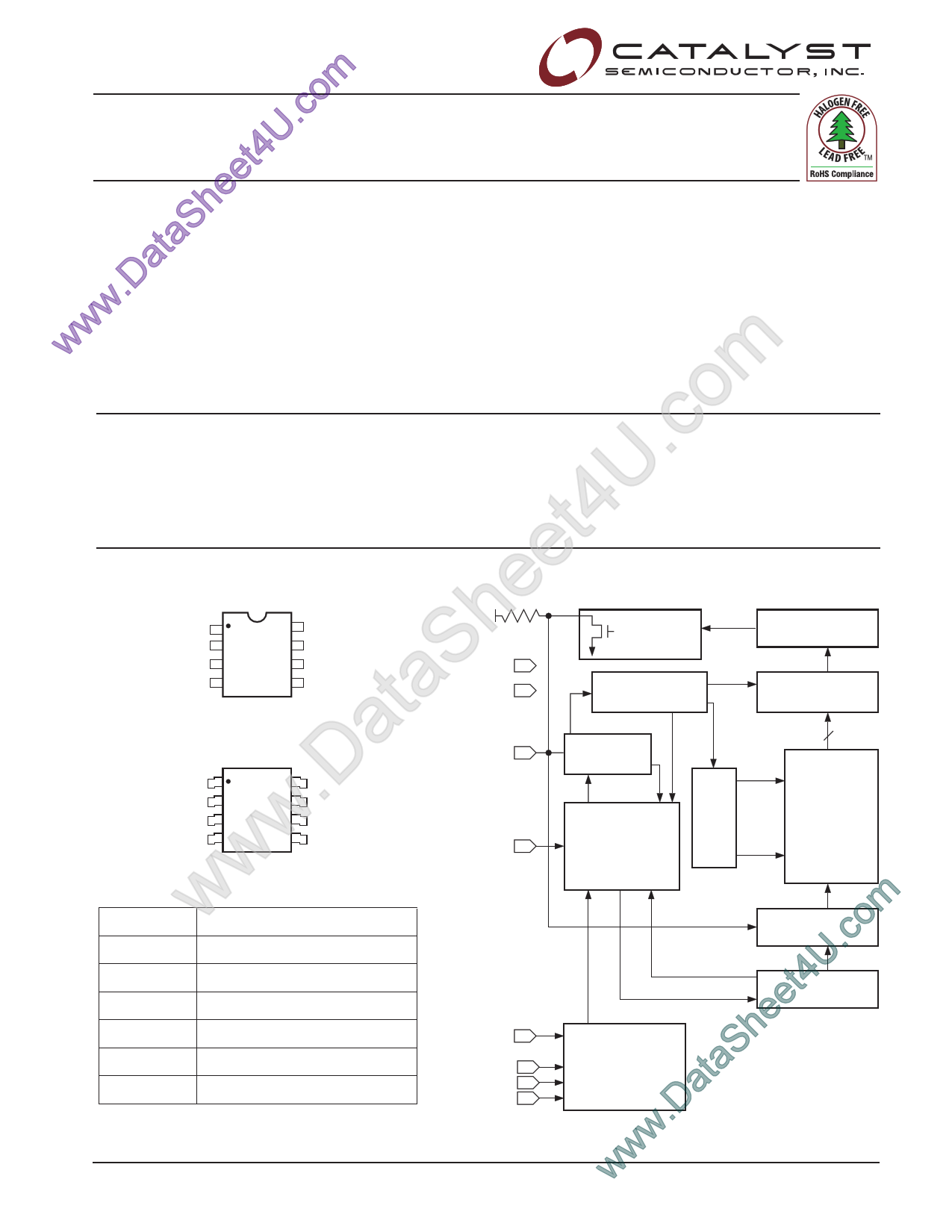
ePIN CONFIGURATION
DIP Package (P, L, GL)
heA0
A1
SA2
VSS
1
2
3
4
8 VCC
7 WP
6 SCL
5 SDA
ataSOIC Package (J, W, K, X, GW, GX)
.DA0
A1
A2
wVSS
1
2
3
4
8 VCC
7 WP
6 SCL
5 SDA
BLOCK DIAGRAM
EXTERNAL LOAD
VCC
VSS
DOUT
ACK
WORD ADDRESS
BUFFERS
SDA
START/STOP
LOGIC
SENSE AMPS
SHIFT REGISTERS
COLUMN
DECODERS
256
E2PROM
XDEC 128/256 128/256 X 256
CONTROL
WP LOGIC
wPIN FUNCTIONS
w omPin Name
Function
.cA0, A1, A2 Device Address Inputs
t4USDA
Serial Data/Address
eSCL Serial Clock
heWP Write Protect
SCL STATE COUNTERS
SVCC +1.8V to +5.5V Power Supply
ataVSS Ground
A0 SLAVE
A1 ADDRESS
A2 COMPARATORS
.D* Catalyst Semiconductor is licensed by Philips Corporation to carry the I2C Bus Protocol.
DATA IN STORAGE
HIGH VOLTAGE/
TIMING CONTROL
24WC32/64 F02
ww© 2005 by Catalyst Semiconductor, Inc.
wCharacteristics subject to change without notice
1
Doc. No. 1039, Rev. G
1 page 
CAT24WC32/64
I2C BUS PROTOCOL
The features of the I2C bus protocol are defined as
follows:
(1) Data transfer may be initiated only when the bus is
not busy.
(2) During a data transfer, the data line must remain
stable whenever the clock line is high. Any changes
in the data line while the clock line is high will be
interpreted as a START or STOP condition.
START Condition
The START Condition precedes all commands to the
device, and is defined as a HIGH to LOW transition of
SDA when SCL is HIGH. The CAT24WC32/64 monitors
the SDA and SCL lines and will not respond until this
condition is met.
STOP Condition
A LOW to HIGH transition of SDA when SCL is HIGH
determines the STOP condition. All operations must end
with a STOP condition.
DEVICE ADDRESSING
The bus Master begins a transmission by sending a
START condition. The Master sends the address of the
particular slave device it is requesting. The four most
significant bits of the 8-bit slave address are fixed as
1010 (Fig. 5). The next three bits (A2, A1, A0) are the
device address bits; up to eight 32K/64K devices may
to be connected to the same bus. These bits must
compare to the hardwired input pins, A2, A1 and A0. The
last bit of the slave address specifies whether a Read or
Write operation is to be performed. When this bit is set
to 1, a Read operation is selected, and when set to 0, a
Write operation is selected.
After the Master sends a START condition and the slave
address byte, the CAT24WC32/64 monitors the bus and
responds with an acknowledge (on the SDA line) when
its address matches the transmitted slave address. The
CAT24WC32/64 then performs a Read or Write opera-
tion depending on the state of the R/W bit.
Acknowledge
After a successful data transfer, each receiving device is
required to generate an acknowledge. The Acknowledg-
ing device pulls down the SDA line during the ninth clock
cycle, signaling that it received the 8 bits of data.
The CAT24WC32/64 responds with an acknowledge
after receiving a START condition and its slave address.
If the device has been selected along with a write
operation, it responds with an acknowledge after receiv-
ing each 8-bit byte.
When the CAT24WC32/64 begins a READ mode it
transmits 8 bits of data, releases the SDA line, and
monitors the line for an acknowledge. Once it receives
this acknowledge, the CAT24WC32/64 will continue to
transmit data. If no acknowledge is sent by the Master,
the device terminates data transmission and waits for a
STOP condition. The master must then issue a stop
condition to return the CAT24WC32/64 to the standby
power mode and place the device in a known state.
Figure 4. Acknowledge Timing
SCL FROM
MASTER
1
89
DATA OUTPUT
FROM TRANSMITTER
DATA OUTPUT
FROM RECEIVER
START
ACKNOWLEDGE
Figure 5. Slave Address Bits
1 0 1 0 A2 A1 A0 R/W
© 2005 by Catalyst Semiconductor, Inc.
Characteristics subject to change without notice
5
5020 FHD F06
5027 FHD F07
Doc. No. 1039, Rev. G
5 Page 
CAT24WC32/64
ORDERING INFORMATION
Prefix
CAT
Device #
24WC32
Suffix
J
I
-1.8 TE13
Rev D(2)
Optional
Company ID
Product
Number
24WC32: 32K
24WC64: 64K
Temperature Range
Blank = Commercial (0˚C to +70˚C)
I = Industrial (-40˚C to +85˚C)
A = Automotive (-40˚ to +105˚C)
E = Extended (-40˚C to +125˚C)
Tape & Reel
Package
P: PDIP
J: SOIC, JEDEC
K: SOIC, EIAJ
L: PDIP (Lead-free, Halogen-free)
W: SOIC, JEDEC (Lead-free, Halogen-free)
X: SOIC, EIAJ (Lead-free, Halogen-free)
GL: PDIP (Lead-free, Halogen-free, NiPdAu lead plating)
GW: SOIC, JEDEC (Lead-free, Halogen-free, NiPdAu lead plating)
GX: SOIC, EIAJ (Lead-free, Halogen-free, NiPdAu lead plating)
Operating Voltage
Blank = 2.5 to 5.5V
1.8 = 1.8 to 5.5V
Die Revision
24WC32: B, D
24WC64: B, D
Notes:
(1) The device used in the above example is a CAT24WC32JI-1.8TE13 (SOIC, Industrial Temperature, 1.8 Volt to 5.5 Volt Operating
Voltage, Tape & Reel)
(2) Product die revision letter is marked on top of the package as a suffix to the production date code (e.g., AYWWB). For additional
information, please contact your Catalyst sales office.
© 2005 by Catalyst Semiconductor, Inc.
Characteristics subject to change without notice
11
Doc. No. 1039, Rev. G
11 Page | ||
| Páginas | Total 12 Páginas | |
| PDF Descargar | [ Datasheet CAT24WC64.PDF ] | |
Hoja de datos destacado
| Número de pieza | Descripción | Fabricantes |
| CAT24WC64 | 32K/64K-Bit I2C Serial CMOS E2PROM | Catalyst Semiconductor |
| CAT24WC64 | (CAT24WC32 / CAT24WC64) 32K / 64K-Bit IC Serial CMOS EEPROM | Catalyst Semiconductor |
| CAT24WC65 | 32K/64K-Bit I2C Serial CMOS E2PROM | Catalyst Semiconductor |
| CAT24WC66 | 64K-bit I2C Serial EEPROM | Catalyst Semiconductor |
| Número de pieza | Descripción | Fabricantes |
| SLA6805M | High Voltage 3 phase Motor Driver IC. |
Sanken |
| SDC1742 | 12- and 14-Bit Hybrid Synchro / Resolver-to-Digital Converters. |
Analog Devices |
|
DataSheet.es es una pagina web que funciona como un repositorio de manuales o hoja de datos de muchos de los productos más populares, |
| DataSheet.es | 2020 | Privacy Policy | Contacto | Buscar |