|
|
|
PDF IRF1503 Data sheet ( Hoja de datos )
| Número de pieza | IRF1503 | |
| Descripción | AUTOMOTIVE MOSFET | |
| Fabricantes | International Rectifier | |
| Logotipo | ||
Hay una vista previa y un enlace de descarga de IRF1503 (archivo pdf) en la parte inferior de esta página. Total 9 Páginas | ||
|
No Preview Available !
PD-94526A
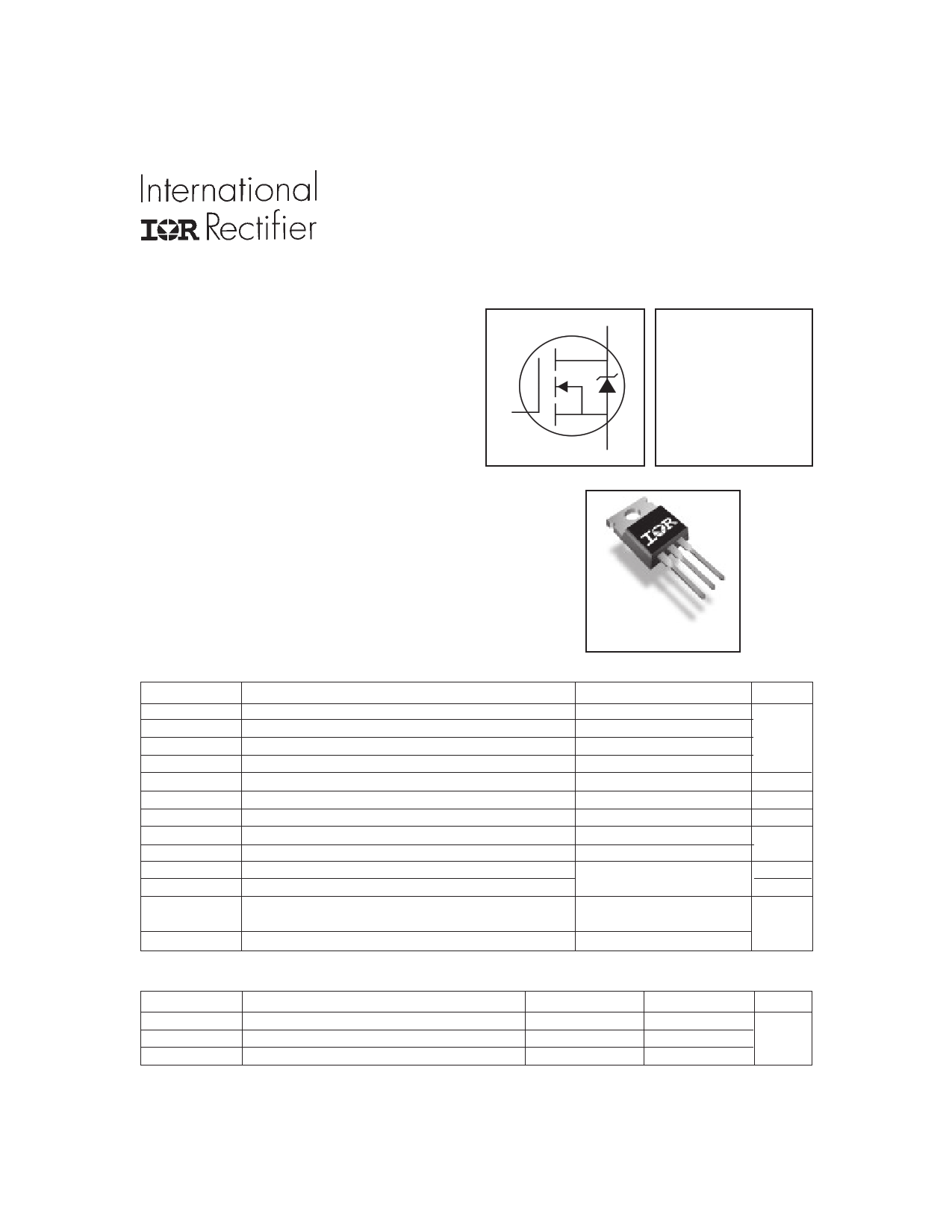
AUTOMOTIVE MOSFET
IRF1503
Typical Applications
● 14V Automotive Electrical Systems
● 14V Electronic Power Steering
Features
● Advanced Process Technology
● Ultra Low On-Resistance
● 175°C Operating Temperature
● Fast Switching
● Repetitive Avalanche Allowed up to Tjmax
G
HEXFET® Power MOSFET
D
VDSS = 30V
RDS(on) = 3.3mΩ
ID = 75A
S
Description
Specifically designed for Automotive applications, this
design of HEXFET® Power MOSFETs utilizes the lastest
processing techniques to achieve extremely low on-
resistance per silicon area. Additional features of this
HEXFET power MOSFET are a 175°C junction operating
temperature, fast switching speed and improved repetitive
avalanche rating. These combine to make this design an
extremely efficient and reliable device for use in Automotive
applications and a wide variety of other applications.
Absolute Maximum Ratings
ID @ TC = 25°C
ID @ TC = 100°C
ID @ TC = 25°C
IDM
PD @TC = 25°C
VGS
EAS
EAS (tested)
IAR
EAR
TJ
TSTG
Parameter
Continuous Drain Current, VGS @ 10V (Silicon limited)
Continuous Drain Current, VGS @ 10V (See Fig.9)
Continuous Drain Current, VGS @ 10V (Package limited)
Pulsed Drain Current
Power Dissipation
Linear Derating Factor
Gate-to-Source Voltage
Single Pulse Avalanche Energy
Single Pulse Avalanche Energy Tested Value
Avalanche Current
Repetitive Avalanche Energy
Operating Junction and
Storage Temperature Range
Soldering Temperature, for 10 seconds
TO-220AB
Max.
240
170
75
960
330
2.2
± 20
510
980
See Fig.12a, 12b, 15, 16
-55 to + 175
300 (1.6mm from case )
Units
A
W
W/°C
V
mJ
A
mJ
°C
Thermal Resistance
RθJC
RθCS
RθJA
Parameter
Junction-to-Case
Case-to-Sink, Flat, Greased Surface
Junction-to-Ambient
www.irf.com
Typ.
–––
0.50
–––
Max.
0.45
–––
62
Units
°C/W
1
12/11/02
1 page 
IRF1503
240
LIMITED BY PACKAGE
200
160
120
80
40
0
25 50 75 100 125 150 175
TC, Case Temperature
( °C)
Fig 9. Maximum Drain Current Vs.
Case Temperature
2.0
I D = 240A
1.5
1.0
0.5
V GS = 10V
0.0
-60 -40 -20 0 20 40 60 80 100 120 140 160 180
TJ, Junction Temperature
( °C)
Fig 10. Normalized On-Resistance
Vs. Temperature
1
D = 0.50
0.1
0.01
0.20
0.10
0.05
0.02
0.01
0.001
0.00001
SINGLE PULSE
(THERMAL RESPONSE)
0.0001
0.001
t1, Rectangular Pulse Duration (sec)
P DM
t1
t2
Notes:
1. Duty factor D =
t1/ t 2
2. Peak T J = P DM x Z thJC + T C
0.01
0.1
Fig 11. Maximum Effective Transient Thermal Impedance, Junction-to-Case
www.irf.com
5
5 Page | ||
| Páginas | Total 9 Páginas | |
| PDF Descargar | [ Datasheet IRF1503.PDF ] | |
Hoja de datos destacado
| Número de pieza | Descripción | Fabricantes |
| IRF150 | N-CHANNEL POWER MOSFETS | Samsung semiconductor |
| IRF150 | N-CHANNEL POWER MOSFET | Seme LAB |
| IRF150 | 40A/ 100V/ 0.055 Ohm/ N-Channel Power MOSFET | Intersil Corporation |
| IRF150 | TRANSISTORS N-CHANNEL(Vdss=100V/ Rds(on)=0.055ohm/ Id= 38A) | International Rectifier |
| Número de pieza | Descripción | Fabricantes |
| SLA6805M | High Voltage 3 phase Motor Driver IC. |
Sanken |
| SDC1742 | 12- and 14-Bit Hybrid Synchro / Resolver-to-Digital Converters. |
Analog Devices |
|
DataSheet.es es una pagina web que funciona como un repositorio de manuales o hoja de datos de muchos de los productos más populares, |
| DataSheet.es | 2020 | Privacy Policy | Contacto | Buscar |