|
|
|
PDF DS1267 Data sheet ( Hoja de datos )
| Número de pieza | DS1267 | |
| Descripción | Dual Digital Potentiometer Chip | |
| Fabricantes | Dallas Semiconducotr | |
| Logotipo | ||
Hay una vista previa y un enlace de descarga de DS1267 (archivo pdf) en la parte inferior de esta página. Total 12 Páginas | ||
|
No Preview Available !
www.dalsemi.com
DS1267
Dual Digital Potentiometer Chip
FEATURES
§ Ultra-low power consumption, quiet,
pumpless design
§ Two digitally controlled, 256-position
potentiometers
§ Serial port provides means for setting and
reading both potentiometers
§ Resistors can be connected in series to
provide increased total resistance
§ 14-pin DIP, 16-pin SOIC, 20-pin TSSOP
packages
§ Resistive elements are temperature
compensated to ±0.3 LSB relative linearity
§ Standard resistance values:
– DS1267-10 ~ 10 kΩ
– DS1267-50 ~ 50 kΩ
– DS1267-100 ~ 100 kΩ
§ Operating Temperature Range:
– Industrial: -40°C to +85°C
PIN DESCRIPTIONS
L0, L1 - Low End of Resistor
H0, H1 - High End of Resistor
W0, W1 - Wiper Terminal of Resistor
VB
SOUT
- Substrate Bias Voltage
- Stacked Configuration Output
RST - Serial Port Reset Input
DQ - Serial Port Data Input
CLK - Serial Port Clock Input
COUT - Cascade Port Output
VCC - +5 Volt Supply
GND - Ground
NC - No Internal Connection
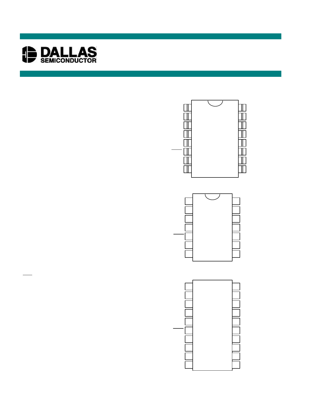
PIN ASSIGNMENT
VB
NC
H1
L1
W1
RST
CLK
GND
1
2
3
4
5
6
7
8
16 VCC
15 NC
14 SOUT
13 W0
12 H0
11 L0
10 COUT
9 DQ
16-Pin SOIC (300-mil)
See Mech. Drawings Section
VB
H1
L1
W1
RST
CLK
GND
1
2
3
4
5
6
7
14 VCC
13 SOUT
12 W0
11 H0
10 L0
9 COUT
8 DQ
14-Pin DIP (300-mil)
See Mech. Drawings Section
1 of 12
VB 1
NC 2
H1 3
20 VCC
19 NC
18 NC
L1 4
W1 5
17 SOUT
16 W0
RST
6
15 H0
CLK
NC
NC
GND
7
8
9
10
14 L0
13 COUT
12 NC
11 DQ
20-Pin TSSOP (173-mil)
102199
1 page 
DS1267
The COUT output of the DS1267 can be used to drive the DQ input of another DS1267. When connecting
multiple devices, the total number of bits transmitted is always 17 times the number of DS1267s in the
daisy chain.
An optional feedback resistor can be placed between the COUT terminal of the last device and the first
DS1267 DQ input, thus allowing the controlling processor to read as well as write data or circularly clock
data through the daisy chain. The value of the feedback or isolation resistor should be in the range from 1
to 10 kohms.
When reading data via the COUT pin and isolation resistor, the DQ line is left floating by the reading
device. When RST is driven high, bit 17 is present on the COUT pin, which is fed back to the input DQ
pin through the isolation resistor. When the CLK input transitions low to high, bit 17 is loaded into the
first position of the I/O shift register and bit 16 becomes present on COUT and DQ of the next device. After
17 bits (or 17 times the number of DS1267s in the daisy chain), the data has shifted completely around
and back to its original position. When RST transitions to the low state to end data transfer, the value (the
same as before the read occurred) is loaded into the wiper-0, wiper-1, and stack select bit I/O register.
ABSOLUTE AND RELATIVE LINEARITY
Absolute linearity is defined as the difference between the actual measured output voltage and the
expected output voltage. Figure 5 presents the test circuit used to measure absolute linearity. Absolute
linearity is given in terms of a minimum increment or expected output when the wiper is moved one
position. In the case of the test circuit, a minimum increment (MI) or one LSB would equal 10/512 volts.
The equation for absolute linearity is given as follows:
(1) ABSOLUTE LINEARITY
AL={VO (actual) - VO (expected)}/MI
Relative Linearity is a measure of error between two adjacent wiper position points and is given in terms
of MI by equation (2).
(2) RELATIVE LINEARITY
RL={VO (n+1) - VO (n)}/MI
Figure 6 is a plot of absolute linearity and relative linearity versus wiper position for the DS1267 at 25°C.
The specification for absolute linearity of the DS1267 is ±0.75 MI typical. The specification for relative
linearity of the DS1267 is ±0.3 MI typical.
5 of 12
102199
5 Page 
(C) END OF COMMUNICATION TRANSACTION
DS1267
DIGITAL OUTPUT LOAD SCHEMATIC Figure 10
11 of 12
102199
11 Page | ||
| Páginas | Total 12 Páginas | |
| PDF Descargar | [ Datasheet DS1267.PDF ] | |
Hoja de datos destacado
| Número de pieza | Descripción | Fabricantes |
| DS1260 | Smart Battery | Dallas Semiconducotr |
| DS1265AB | 8M Nonvolatile SRAM | Maxim Integrated Products |
| DS1265W | 3.3V 8Mb Nonvolatile SRAM | Dallas Semiconducotr |
| DS1265Y | 8M Nonvolatile SRAM | Maxim Integrated Products |
| Número de pieza | Descripción | Fabricantes |
| SLA6805M | High Voltage 3 phase Motor Driver IC. |
Sanken |
| SDC1742 | 12- and 14-Bit Hybrid Synchro / Resolver-to-Digital Converters. |
Analog Devices |
|
DataSheet.es es una pagina web que funciona como un repositorio de manuales o hoja de datos de muchos de los productos más populares, |
| DataSheet.es | 2020 | Privacy Policy | Contacto | Buscar |