|
|
|
PDF TC7129 Data sheet ( Hoja de datos )
| Número de pieza | TC7129 | |
| Descripción | 4-1/2 Digit Analog-to-Digital Converters with On-Chip LCD Drivers | |
| Fabricantes | Microchip | |
| Logotipo | ||
Hay una vista previa y un enlace de descarga de TC7129 (archivo pdf) en la parte inferior de esta página. Total 24 Páginas | ||
|
No Preview Available !
TC7129
4-1/2 Digit Analog-to-Digital Converters with
On-Chip LCD Drivers
Features
• Count Resolution: ±19,999
• Resolution on 200mV Scale: 10µV
• True Differential Input and Reference
• Low Power Consumption: 500µA at 9V
• Direct LCD Driver for 4-1/2 Digits, Decimal Points,
Low Battery Indicator, and Continuity Indicator
• Over Range and Under Range Outputs
• Range Select Input: 10:1
• High Common Mode Rejection Ratio: 110dB
• External Phase Compensation Not Required
Applications
• Full Featured Multimeters
• Digital Measurement Devices
Device Selection Table
Package
Code
TC7129CPL
TC7129CKW
TC7129CLW
Pin
Layout
Normal
Formed
–
Package
40-Pin PDIP
44-Pin PQFP
44-Pin PLCC
Temperature
Range
0°C to +70°C
0°C to +70°C
0°C to +70°C
General Description
The TC7129 is a 4-1/2 digit analog-to-digital converter
(ADC) that directly drives a multiplexed liquid crystal
display (LCD). Fabricated in high performance, low
power CMOS, the TC7129 ADC is designed specifi-
cally for high resolution, battery powered digital multi-
meter applications. The traditional dual slope method
of A/D conversion has been enhanced with a succes-
sive integration technique to produce readings accu-
rate to better than 0.005% of full scale, and resolution
down to 10µV per count.
The TC7129 includes features important to multimeter
applications. It detects and indicates low battery condi-
tion. A continuity output drives an annunciator on the
display, and can be used with an external driver to
sound an audible alarm. Over range and under range
outputs and a range change input provide the ability to
create auto-ranging instruments. For snapshot read-
ings, the TC7129 includes a latch-and-hold input to
freeze the present reading. This combination of features
makes the TC7129 the ideal choice for full featured
multimeter and digital measurement applications.
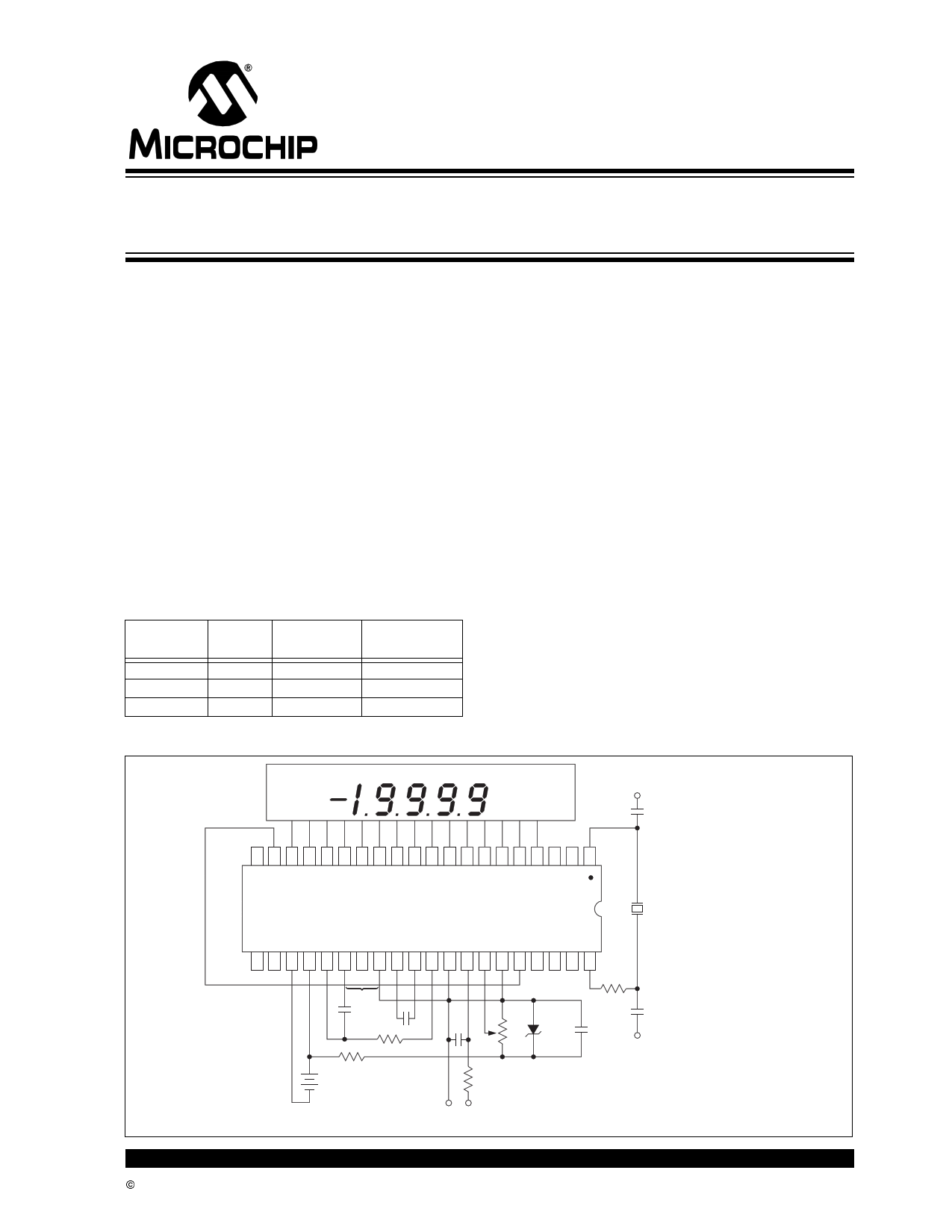
Typical Application
Low Battery
Continuity
V+
5pF
20 19 18 17 16 15 14 13 12 11 10 9 8 7 6 5 4 3 2 1
TC7129
120kHz
21 22 23 24 25 26 27 28 29 30 31 32 33 34 35 36 37 38 39 40
330kΩ
*
0.1µF
1µF
150kΩ
+ 10kΩ
9V
+
0.1
µF
20
kΩ
0.1µF
10pF
V+
100kΩ
– + *Note: RC network between Pins 26 and 28 is not required.
VIN
© 2002 Microchip Technology Inc.
DS21459B-page 1
1 page 
TC7129
2.0 PIN DESCRIPTIONS
The descriptions of the pins are listed in Table 2-1.
TABLE 2-1: PIN FUNCTION TABLE
Pin No.
Pin No.
Pin No.
40-Pin PDIP 44-Pin PQFP 44-Pin PLCC
Symbol
Function
1 40
2 41
3 42
4 43
5 44
61
72
83
94
10 5
11 7
12 8
13 9
14 10
15 11
16 12
17 13
18 14
19 15
20 16
21 18
22 19
23 20
24 21
25 22
26 23
27 24
28 25
29 26
30 27
31 29
32 30
33 31
34 32
35 33
2
OSC1
Input to first clock inverter.
3
OSC3
Output of second clock inverter.
4 ANNUNCIATOR Backplane square wave output for driving annunciators.
5 B1, C1, CONT Output to display segments.
6 A1, G1, D1 Output to display segments.
7 F1, E1, DP1 Output to display segments.
8 B2, C2, LO BATT Output to display segments.
9 A2, G2, D2 Output to display segments.
10 F2, E2, DP2 Output to display segments.
11 B3, C3, MINUS Output to display segments.
13 A3, G3, D3 Output to display segments.
14 F3, E3, DP3 Output to display segments.
15 B4, C4, BC5 Output to display segments.
16 A4, D4, G4 Output to display segments.
17 F4, E4, DP4 Output to display segments.
18 BP3 Backplane #3 output to display.
19 BP2 Backplane #2 output to display.
20 BP1 Backplane #1 output to display.
21
VDISP
Negative rail for display drivers.
22
DP4/OR
Input: When HI, turns on most significant decimal point.
Output: Pulled HI when result count exceeds ±19,999.
24
DP3/UR
Input: Second most significant decimal point on when HI.
Output: Pulled HI when result count is less than ±1000.
25 LATCH/HOLD Input: When floating, ADC operates in the Free Run mode. When
pulled HI, the last displayed reading is held. When pulled LO, the
result counter contents are shown incrementing during the
de-integrate phase of cycle.
Output: Negative going edge occurs when the data latches are
updated. Can be used for converter status signal.
26 V- Negative power supply terminal.
27 V+ Positive power supply terminal and positive rail for display drivers.
28
INT IN
Input to integrator amplifier.
29 INT OUT Output of integrator amplifier.
30 CONTINUITY Input: When LO, continuity flag on the display is OFF. When HI,
continuity flag is ON.
Output: HI when voltage between inputs is less than +200mV. LO
when voltage between inputs is more than +200mV.
31 COMMON Sets Common mode voltage of 3.2V below V+ for DE, 10X, etc.
Can be used as pre-regulator for external reference.
32
CREF+
Positive side of external reference capacitor.
33
CREF-
Negative side of external reference capacitor.
35 BUFFER Output of buffer amplifier.
36
IN LO
Negative input voltage terminal.
37
IN HI
Positive input voltage terminal.
38
REF HI
Positive reference voltage.
39
REF LO
Negative reference voltage
© 2002 Microchip Technology Inc.
DS21459B-page 5
5 Page 
TC7129
FIGURE 4-6:
TEMPERATURE COMPENSATING CIRCUITS
V+
V+
1N4148
5kΩ
75kΩ
39kΩ
200kΩ
–
+
24
TC7129
19 VDISP
36 DGND
23
39kΩ
24
20kΩ
2N2222 TC7129
18kΩ
19
VDISP
36
DGND
23
V-
4.8 RC Oscillator
For applications in which 3-1/2 digit (100µV) resolution
is sufficient, an RC oscillator is adequate. A recom-
mended value for the capacitor is 51pF. Other values
can be used as long as they are sufficiently larger than
the circuit parasitic capacitance. The resistor value is
calculated as:
EQUATION 4-1:
R = 0.45
Freq * C
For 120kHz frequency and C = 51pF, the calculated
value of R is 75kΩ. The RC oscillator and the crystal
oscillator circuits are shown in Figure 4-7.
FIGURE 4-7:
OSCILLATOR CIRCUITS
1
5pF
V+
120kHz
40
270kΩ
10pF
TC7129
2
V+
V-
4.9 Measuring Techniques
Two important techniques are used in the TC7129: suc-
cessive integration and digital auto-zeroing. Succes-
sive integration is a refinement to the traditional dual
slope conversion technique.
4.10 Dual Slope Conversion
A dual slope conversion has two basic phases: inte-
grate and de-integrate. During the integrate phase, the
input signal is integrated for a fixed period of time; the
integrated voltage level is thus proportional to the input
voltage. During the de-integrate phase, the integrated
voltage is ramped down at a fixed slope, and a counter
counts the clock cycles until the integrator voltage
crosses zero. The count is a measurement of the time
to ramp the integrated voltage to zero, and is, there-
fore, proportional to the input voltage being measured.
This count can then be scaled and displayed as a mea-
surement of the input voltage. Figure 4-8 shows the
phases of the dual slope conversion.
FIGURE 4-8:
Integrate
DUAL SLOPE
CONVERSION
De-integrate
TC7129
1 40 2
75kΩ
51pF
© 2002 Microchip Technology Inc.
Zero
Crossing
Time
The dual slope method has a fundamental limitation.
The count can only stop on a clock cycle, so that mea-
surement accuracy is limited to the clock frequency. In
addition, a delay in the zero crossing comparator can
add to the inaccuracy. Figure 4-9 shows these errors in
an actual measurement.
DS21459B-page 11
11 Page | ||
| Páginas | Total 24 Páginas | |
| PDF Descargar | [ Datasheet TC7129.PDF ] | |
Hoja de datos destacado
| Número de pieza | Descripción | Fabricantes |
| TC7126 | 3-1/2 Digit Analog-to-Digital Converters | Microchip |
| TC7126 | 3-1/2 DIGIT ANALOG-TO-DIGITAL CONVERTERS | TelCom |
| TC7129 | 4-1/2 Digit Analog-to-Digital Converters with On-Chip LCD Drivers | Microchip |
| TC7129 | 4-1/2 DIGIT ANALOG-TO-DIGITAL CONVERTER WITH ON-CHIP LCD DRIVERS | TelCom |
| Número de pieza | Descripción | Fabricantes |
| SLA6805M | High Voltage 3 phase Motor Driver IC. |
Sanken |
| SDC1742 | 12- and 14-Bit Hybrid Synchro / Resolver-to-Digital Converters. |
Analog Devices |
|
DataSheet.es es una pagina web que funciona como un repositorio de manuales o hoja de datos de muchos de los productos más populares, |
| DataSheet.es | 2020 | Privacy Policy | Contacto | Buscar |