|
|
|
PDF WM8714 Data sheet ( Hoja de datos )
| Número de pieza | WM8714 | |
| Descripción | 24 Bit / 96 Khz Stereo DAC | |
| Fabricantes | Wolfson Microelectronics | |
| Logotipo | ||
Hay una vista previa y un enlace de descarga de WM8714 (archivo pdf) en la parte inferior de esta página. Total 15 Páginas | ||
|
No Preview Available !
w
WM8714
24-bit, 96kHz Stereo DAC
DESCRIPTION
The WM8714 is a high performance stereo DAC designed
for audio applications such as DVD, home theatre systems,
and digital TV. The WM8714 supports data input word
lengths from 16 to 24-bits and sampling rates up to 96kHz.
The WM8714 consists of a serial interface port, digital
interpolation filters, multi-bit sigma delta modulators and
stereo DAC in a 14-pin SOIC package.
The WM8714 has a hardware control interface for selection
of audio data interface format, mute and de-emphasis. The
WM8714 supports I2S, and right Justified audio data
interfaces.
The WM8714 is an ideal device to interface to AC-3,
DTS, and MPEG audio decoders for surround sound
applications, or for use in DVD players.
FEATURES
• Stereo DAC
• Audio Performance
- 95dB SNR (‘A’ weighted @ 48kHz) DAC
- -90dB THD
• DAC Sampling Frequency: 8kHz – 96kHz
• Pin Selectable Audio Data Interface Format
- I2S, Right Justified or DSP
• 3 - 5V Supply Operation
• 14-pin SOIC Package
• Pin Compatible with WM8725
APPLICATIONS
• DVD Players
• Digital TV
• Digital Set Top Boxes
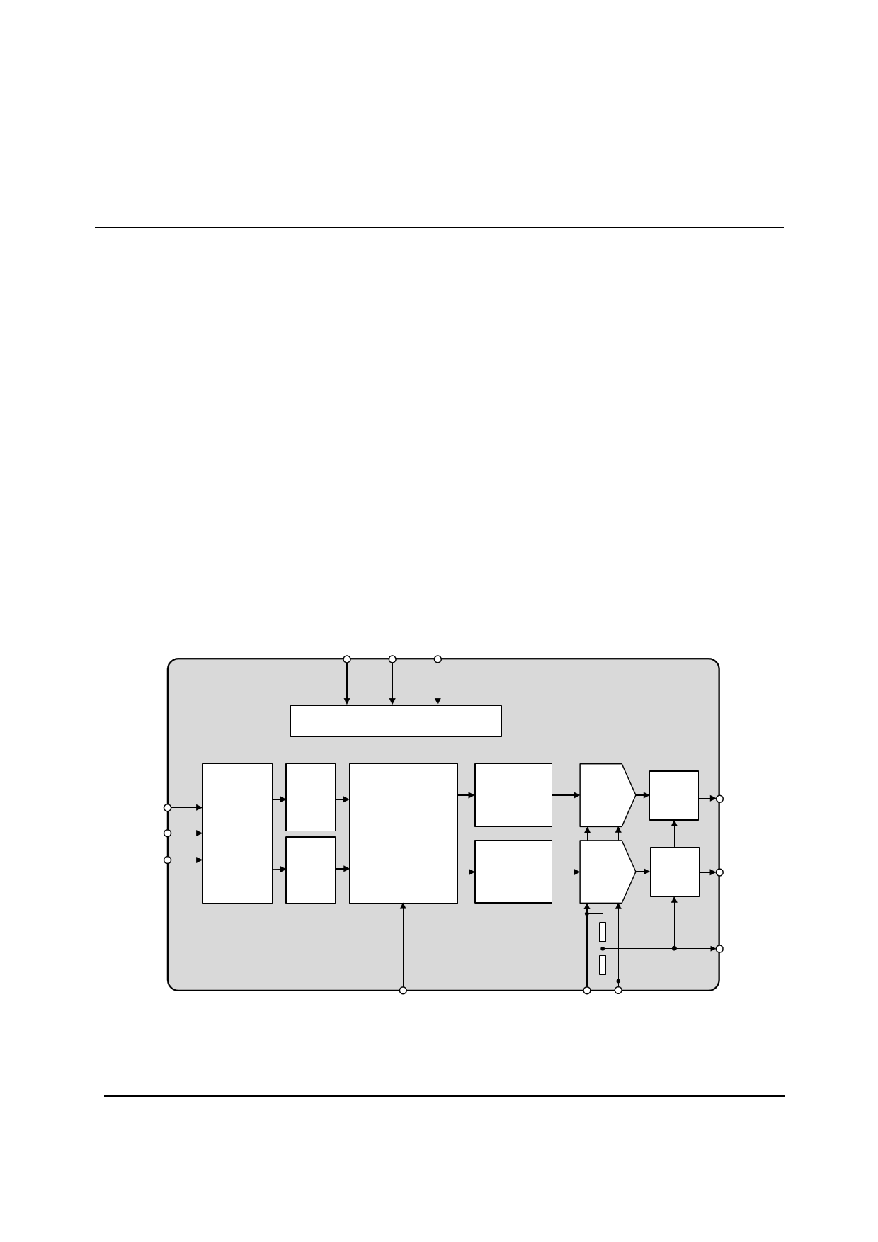
BLOCK DIAGRAM
FORMAT MUTE DEEMPH
CONTROL INTERFACE
W
WM8714
BCKIN
LRCIN
DIN
SERIAL
INTERFACE
MUTE
MUTE
DIGITAL FILTERS
SIGMA
DELTA
MODULATOR
SIGMA
DELTA
MODULATOR
RIGHT
DAC
LEFT
DAC
LOW
PASS
FILTER
VOUTR
LOW
PASS
FILTER
VOUTL
MCLK
VDD GND
CAP
WOLFSON MICROELECTRONICS LTD
w :: www.wolfsonmicro.com
Production Data, July 2002, Rev 1.3
Copyright 2002 Wolfson Microelectronics Ltd.
1 page 
WM8714
Test Conditions
VDD = 5V, GND = 0V, TA = +25oC, fs = 48kHz, MCLK = 256fs unless otherwise stated.
PARAMETER
SYMBOL TEST CONDITIONS
MIN
Analogue Output Levels
Output level
Load = 10k ohms,
0dBFS
Load = 10k ohms,
0dBFS,
(VDD = 3.3V)
Gain mismatch
channel-to-channel
Minimum resistance load
To midrail or a.c.
coupled
To midrail or a.c.
coupled
(VDD = 3.3V)
Maximum capacitance load
5V or 3.3V
Output d.c. level
Power On Reset (POR)
POR threshold
TYP
1.1
0.72
±1
1
1
100
VDD/2
1.8
Production Data
MAX
UNIT
VRMS
VRMS
%FSR
kohms
kohms
pF
V
V
Notes:
1. Ratio of output level with 1kHz full scale input, to the output level with all zeros into the digital input, measured ‘A’ weighted
over a 20Hz to 20kHz bandwidth.
2. All performance measurements done with 20kHz low pass filter, and where noted an A-weight filter. Failure to use such a
filter will result in higher THD+N and lower SNR and Dynamic Range readings than are found in the Electrical
Characteristics. The low pass filter removes out of band noise; although it is not audible it may affect dynamic specification
values.
3. CAP pin decoupled with 10uF and 0.1uF capacitors (smaller values may result in reduced performance).
TERMINOLOGY
1. Signal-to-noise ratio (dB) - SNR is a measure of the difference in level between the full scale output and the output with no
signal applied. (No Auto-zero or Automute function is employed in achieving these results).
2. Dynamic range (dB) - DNR is a measure of the difference between the highest and lowest portions of a signal. Normally a
THD+N measurement at 60dB below full scale. The measured signal is then corrected by adding the 60dB to it. (e.g.
THD+N @ -60dB= -32dB, DR= 92dB).
3. THD+N (dB) - THD+N is a ratio, of the rms values, of (Noise + Distortion)/Signal.
4. Stop band attenuation (dB) - Is the degree to which the frequency spectrum is attenuated (outside audio band).
5. Channel Separation (dB) - Also known as Cross-Talk. This is a measure of the amount one channel is isolated from the
other. Normally measured by sending a full scale signal down one channel and measuring the other.
w
PD Rev 1.3 July 2002
5
5 Page 
WM8714
Production Data
DE-EMPHASIS CONTROL
DEM (pin 12) is an input control for selection of de-emphasis filtering to be applied.
DEEMPH
0
1
Table 4 De-emphasis Control
DE-EMPHASIS
Off
On
DIGITAL FILTER CHARACTERISTICS
PARAMETER
Passband Edge
Passband Ripple
Stopband Attenuation
SYMBOL
TEST CONDITIONS
-3dB
f < 0.444fs
f > 0.555fs
Table 5 Digital Filter Characteristics
MIN
-40
TYP
0.487fs
MAX
±0.25
UNIT
dB
dB
w
PD Rev 1.3 July 2002
11
11 Page | ||
| Páginas | Total 15 Páginas | |
| PDF Descargar | [ Datasheet WM8714.PDF ] | |
Hoja de datos destacado
| Número de pieza | Descripción | Fabricantes |
| WM8711 | Internet Audio DAC with Integrated Headphone Driver | Wolfson Microelectronics plc |
| WM8711 | portable digital audio solutions | Wolfson Microelectronics plc |
| WM8711BL | Ultra-Small Audio DAC | Wolfson Microelectronics |
| WM8711L | Internet Audio DAC | Wolfson Microelectronics |
| Número de pieza | Descripción | Fabricantes |
| SLA6805M | High Voltage 3 phase Motor Driver IC. |
Sanken |
| SDC1742 | 12- and 14-Bit Hybrid Synchro / Resolver-to-Digital Converters. |
Analog Devices |
|
DataSheet.es es una pagina web que funciona como un repositorio de manuales o hoja de datos de muchos de los productos más populares, |
| DataSheet.es | 2020 | Privacy Policy | Contacto | Buscar |