|
|
|
PDF DIM800DDM12 Data sheet ( Hoja de datos )
| Número de pieza | DIM800DDM12 | |
| Descripción | Dual Switch IGBT Module Preliminary Information | |
| Fabricantes | Dynex | |
| Logotipo | ||
Hay una vista previa y un enlace de descarga de DIM800DDM12 (archivo pdf) en la parte inferior de esta página. Total 10 Páginas | ||
|
No Preview Available !
DIM800DDM12-A000
FEATURES
s 10µs Short Circuit Withstand
s High Thermal Cycling Capability
s Non Punch Through Silicon
s Isolated MMC Base with AlN Substrates
DIM800DDM12-A000
Dual Switch IGBT Module
Preliminary Information
DS5528-1.1 March 2002
KEY PARAMETERS
VCES
1200V
VCE(sat)*
(typ)
2.2V
IC
(max)
800A
IC(PK)
(max)
1600A
*(measured at the power busbars and not the auxiliary terminals)
APPLICATIONS
s Inverters
s Motor Controllers
s Traction Drives
The Powerline range of modules includes half bridge, dual
and single switch configurations covering voltages from 600V to
3300V and currents up to 2400A.
The DIM800DDM12-A000 is a dual switch 1200V, n channel
enhancement mode, insulated gate bipolar transistor (IGBT)
module. The IGBT has a wide reverse bias safe operating area
(RBSOA) plus full 10µs short circuit withstand. This module is
optimised applications requiring high thermal cycling capability.
The module incorporates an electrically isolated base plate
and low inductance construction enabling circuit designers to
optimise circuit layouts and utilise grounded heat sinks for safety.
ORDERING INFORMATION
Order As:
DIM800DDM12-A000
Note: When ordering, please use the whole part number.
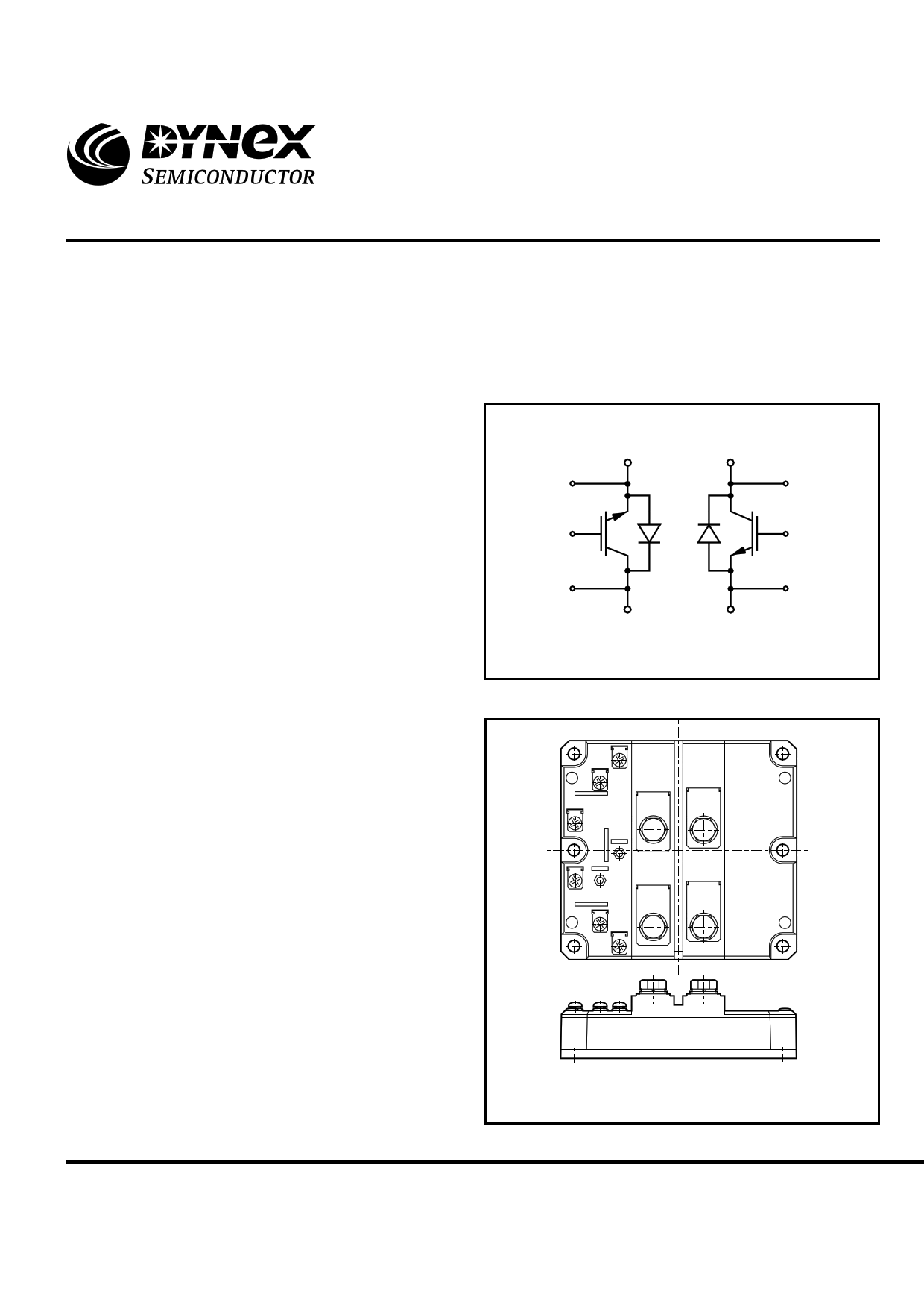
5(E1)
6(G1)
7(C1)
1(E1)
3(C1)
2(C2)
12(C2)
11(G2)
10(E2)
4(E2)
Fig. 1 Dual switch circuit diagram
5
6
7
8
3
9
12
11
10
4
1
2
Outline type code: D
(See package details for further information)
Fig. 2 Electrical connections - (not to scale)
Caution: This device is sensitive to electrostatic discharge. Users should follow ESD handling procedures.
www.dynexsemi.com
1/10
1 page 
ELECTRICAL CHARACTERISTICS
T = 25˚C unless stated otherwise
case
Symbol
Parameter
td(off)
tf
E
OFF
td(on)
tr
EON
Q
g
Qrr
Irr
E
REC
Turn-off delay time
Fall time
Turn-off energy loss
Turn-on delay time
Rise time
Turn-on energy loss
Gate charge
Diode reverse recovery charge
Diode reverse current
Diode reverse recovery energy
Tcase = 125˚C unless stated otherwise
Symbol
Parameter
t
d(off)
tf
EOFF
td(on)
t
r
EON
Q
rr
Irr
EREC
Turn-off delay time
Fall time
Turn-off energy loss
Turn-on delay time
Rise time
Turn-on energy loss
Diode reverse recovery charge
Diode reverse current
Diode reverse recovery energy
DIM800DDM12-A000
Test Conditions
I = 800A
C
VGE = ±15V
VCE = 600V
RG(ON) = RG(OFF) = 2.7Ω
L ~ 100nH
IF = 800A, VR = 600V,
dIF/dt = 4200A/µs
Min. Typ. Max. Units
- 1250 -
ns
- 170 - ns
- 130 - mJ
- 250 - ns
- 250 - ns
- 80 - mJ
- 9.0 - µC
- 80 - µC
- 380 -
A
- 30 - mJ
Test Conditions
IC = 800A
VGE = ±15V
V = 600V
CE
RG(ON) = RG(OFF) = 2.7Ω
L ~ 100nH
I = 800A, V = 600V,
FR
dIF/dt = 4000A/µs
Min. Typ. Max. Units
- 1500 -
ns
- 200 - ns
- 160 - mJ
- 400 - ns
- 220 - ns
- 120 - mJ
- 160 - µC
- 450 -
A
- 60 - mJ
Caution: This device is sensitive to electrostatic discharge. Users should follow ESD handling procedures.
www.dynexsemi.com
5/10
5 Page | ||
| Páginas | Total 10 Páginas | |
| PDF Descargar | [ Datasheet DIM800DDM12.PDF ] | |
Hoja de datos destacado
| Número de pieza | Descripción | Fabricantes |
| DIM800DDM12 | Dual Switch IGBT Module Preliminary Information | Dynex |
| DIM800DDM17-A000 | Dual Switch IGBT Module | Dynex |
| Número de pieza | Descripción | Fabricantes |
| SLA6805M | High Voltage 3 phase Motor Driver IC. |
Sanken |
| SDC1742 | 12- and 14-Bit Hybrid Synchro / Resolver-to-Digital Converters. |
Analog Devices |
|
DataSheet.es es una pagina web que funciona como un repositorio de manuales o hoja de datos de muchos de los productos más populares, |
| DataSheet.es | 2020 | Privacy Policy | Contacto | Buscar |