|
|
|
PDF 27C010 Data sheet ( Hoja de datos )
| Número de pieza | 27C010 | |
| Descripción | 1 Megabit 128K x 8 OTP CMOS EPROM | |
| Fabricantes | ATMEL Corporation | |
| Logotipo | ||
Hay una vista previa y un enlace de descarga de 27C010 (archivo pdf) en la parte inferior de esta página. Total 9 Páginas | ||
|
No Preview Available !
AT27C010/L
Features
Fast Read Access Time - 45 ns
•• Low Power CMOS Operation
100 µA max. Standby
25 mA max. Active at 5 MHz (AT27C010L)
35 mA max. Active at 5 MHz (AT27C010)
• JEDEC Standard Packages
32-Lead 600-mil PDIP
32-Lead PLCC
32-Lead TSOP
• 5V ± 10% Supply
• High Reliability CMOS Technology
2000V ESD Protection
200 mA Latchup Immunity
• Rapid™ Programming Algorithm - 100 µs/byte (typical)
CMOS and TTL Compatible Inputs and Outputs
• Integrated Product Identification Code
•• Commercial and Industrial Temperature Ranges
Description
The AT27C010/L is a low-power, high performance 1,048,576 bit one-time program-
mable read only memory (OTP EPROM) organized as 128K by 8 bits. They require
only one 5V power supply in normal read mode operation. Any byte can be accessed
in less than 45 ns, eliminating the need for speed reducing WAIT states on high per-
formance microprocessor systems.
Two power versions are offered. In read mode, the AT27C010 typically consumes 25
mA while the AT27C010L requires only 8 mA. Standby mode supply current for both
parts is typically less than 10 µA.
(continued)
1 Megabit
(128K x 8)
OTP
CMOS EPROM
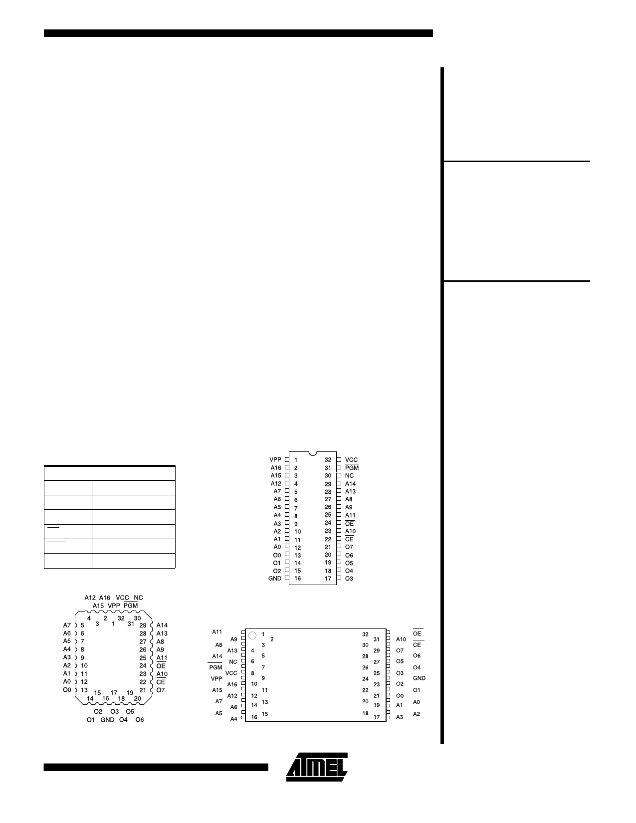
Pin Configurations
Pin Name
A0 - A16
O0 - O7
CE
OE
PGM
NC
Function
Addresses
Outputs
Chip Enable
Output Enable
Program Strobe
No Connect
PLCC Top View
PDIP Top View
AT27C010/L
TSOP Top View
Type 1
0321I
3-153
1 page 
AC Waveforms for Read Operation (1)
AT27C010/L
Notes: 1. Timing measurement reference level is 1.5V for -45
and -55 devices. Input AC drive levels are VIL =
0.0V and VIH = 3.0V. Timing measurement refer-
ence levels for all other speed grades are VOL =
0.8V and VOH = 2.0V. Input AC drive levels are VIL
= 0.45V and VIH = 2.4V.
2. OE may be delayed up to tCE - tOE after the falling
edge of CE without impact on tCE.
3. OE may be delayed up to tACC - tOE after the address is valid
without impact on tACC.
4. This parameter is only sampled and is not 100% tested.
5. Output float is defined as the point when data is no longer
driven.
Input Test Waveforms and Measurement Levels
For -45 and -55 devices
only:
Output Test Load
For -70, -90, -12, -15,
and -20 devices:
tR, tF < 5 ns (10% to 90%)
tR, tF < 20 ns (10% to 90%)
Note: CL = 100 pF including
jig capacitance, except for the
-45 and -55 devices, where
CL= 30 pF.
Pin Capacitance (f = 1 MHz, T = 25°C) (1)
Typ
Max
Units
Conditions
CIN 4
8 pF VIN = 0V
COUT
8
12 pF VOUT = 0V
Note: 1. Typical values for nominal supply voltage. This parameter is only sampled and is not 100% tested.
3-157
5 Page | ||
| Páginas | Total 9 Páginas | |
| PDF Descargar | [ Datasheet 27C010.PDF ] | |
Hoja de datos destacado
| Número de pieza | Descripción | Fabricantes |
| 27C010 | 1 /048 /576-Bit (128K x 8) High Performance CMOS EPROM | Fairchild |
| 27C010 | 1 Megabit 128K x 8 OTP CMOS EPROM | ATMEL Corporation |
| 27C010 | 1M (128K x 8) CHMOS EPROM | Intel |
| Número de pieza | Descripción | Fabricantes |
| SLA6805M | High Voltage 3 phase Motor Driver IC. |
Sanken |
| SDC1742 | 12- and 14-Bit Hybrid Synchro / Resolver-to-Digital Converters. |
Analog Devices |
|
DataSheet.es es una pagina web que funciona como un repositorio de manuales o hoja de datos de muchos de los productos más populares, |
| DataSheet.es | 2020 | Privacy Policy | Contacto | Buscar |