|
|
|
PDF OPA2690 Data sheet ( Hoja de datos )
| Número de pieza | OPA2690 | |
| Descripción | Low-Power / Single-Supply / Wideband Operational Amplifier | |
| Fabricantes | Burr-Brown | |
| Logotipo | ||
Hay una vista previa y un enlace de descarga de OPA2690 (archivo pdf) en la parte inferior de esta página. Total 30 Páginas | ||
|
No Preview Available !
OPA2690
SBOS238E − JUNE 2002 − REVISED MAY 2006
Dual, Wideband, Voltage-Feedback
OPERATIONAL AMPLIFIER with Disable
FEATURES
D FLEXIBLE SUPPLY RANGE:
+5V to +12V Single Supply
±2.5V to ±6V Dual Supply
D WIDEBAND +5V OPERATION: 220MHz (G = 2)
D HIGH OUTPUT CURRENT: 190mA
D OUTPUT VOLTAGE SWING: ±4.0V
D HIGH SLEW RATE: 1800V/µs
D LOW SUPPLY CURRENT: 5.5mA/ch
D LOW DISABLED CURRENT: 100µA/ch
APPLICATIONS
D VIDEO LINE DRIVING
D xDSL LINE DRIVER/RECEIVER
D HIGH-SPEED IMAGING CHANNELS
D ADC BUFFERS
D PORTABLE INSTRUMENTS
D TRANSIMPEDANCE AMPLIFIERS
D ACTIVE FILTERS
+5V 100Ω
+2.5V
2kΩ
+2.5V
100pF
0.1µF +5V
1 /2
O PA2690
499Ω
2kΩ
REFB
REFT
0.1µF
499Ω
1kΩ 35Ω
IN
VIN
499Ω
1kΩ
2.5VCM
2VPP
35Ω
10pF
AD S82 5
IN
10pF
10−Bit
40 M SP S
+2.5V
1 /2
O PA2690
499Ω
Clock
Single-Supply Differential ADC Driver
DESCRIPTION
The OPA2690 represents a major step forward in
unity-gain stable, voltage-feedback op amps. A new
internal architecture provides slew rate and full-power
bandwidth previously found only in wideband,
current-feedback op amps. A new output stage
architecture delivers high currents with a minimal
headroom requirement. These give exceptional
single-supply operation. Using a single +5V supply, the
OPA2690 can deliver a 1V to 4V output swing with over
120mA drive current and 150MHz bandwidth. This
combination of features makes the OPA2690 an ideal
RGB line driver or single-supply Analog-to-Digital
Converter (ADC) input driver.
The low 5.5mA/ch supply current of the OPA2690 is
precisely trimmed at +25°C. This trim, along with low
temperature drift, ensures lower maximum supply current
than competing products. System power may be reduced
further using the optional disable control pin. Leaving this
disable pin open, or holding it HIGH, will operate the
OPA2690I-14D normally. If pulled LOW, the
OPA2690I-14D supply current drops to less than
200µA/ch while the output goes to a high-impedance
state.
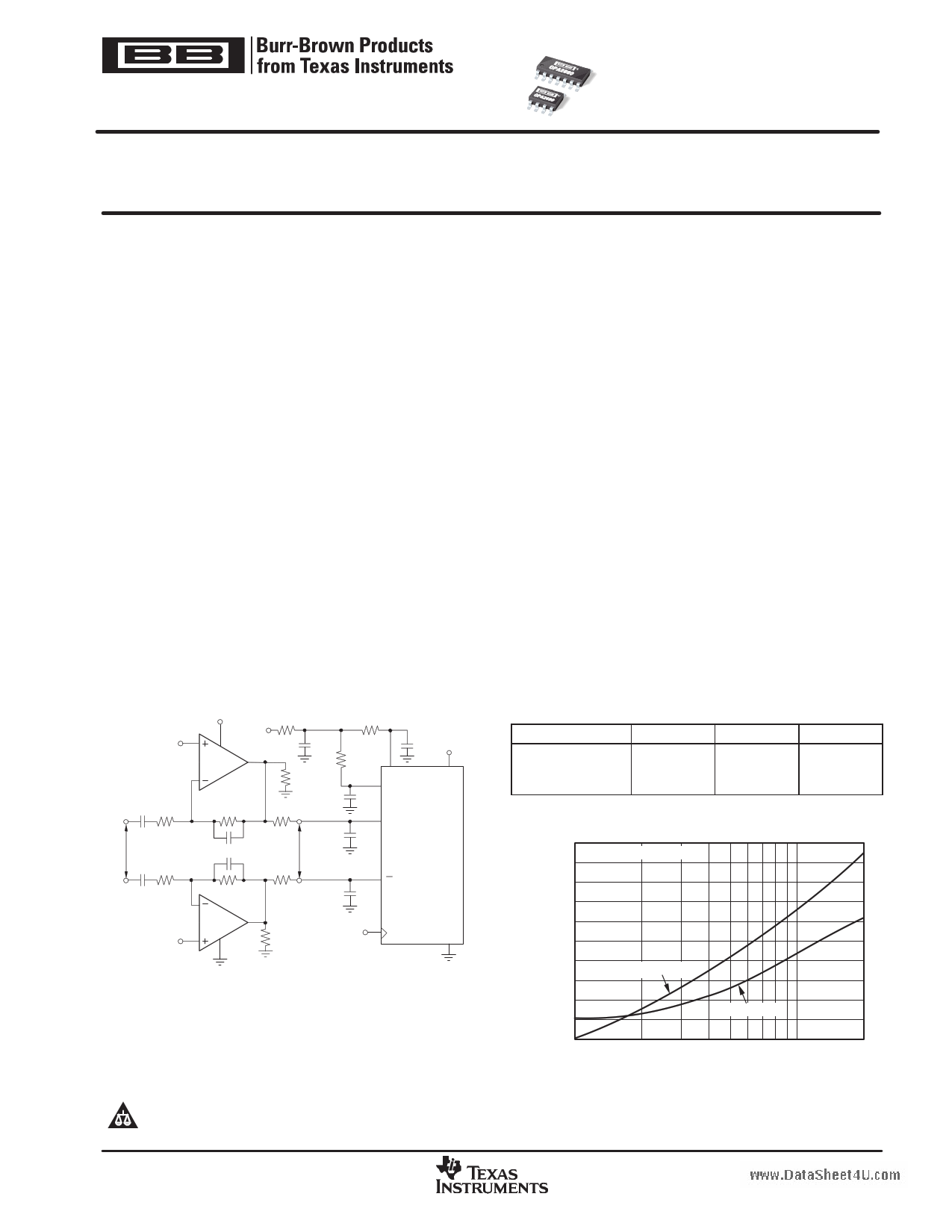
OPA2690 RELATED PRODUCTS
Voltage-Feedback
Current-Feedback
Fixed Gain
SINGLES
OPA2690
OPA691
OPA692
DUALS
OPA2680
OPA2691
—
TRIPLES
OPA3690
OPA3691
OPA3692
HARMONIC DISTORTION vs FREQUENCY
FOR THE SINGLE−SUPPLY ADC DRIVER
− 50
− 55 2VPP Differential Output
− 60
− 65
− 70
− 75
− 80
3rd−Harmonic
− 85
− 90
2nd−Harmonic
− 95
−100
1
10
Frequency (MHz)
20
Please be aware that an important notice concerning availability, standard warranty, and use in critical applications of Texas Instruments
semiconductor products and disclaimers thereto appears at the end of this data sheet.
All trademarks are the property of their respective owners.
PRODUCTION DATA information is current as of publication date. Products
conform to specifications per the terms of Texas Instruments standard warranty.
Production processing does not necessarily include testing of all parameters.
Copyright 2002−2006, Texas Instruments Incorporated
www.ti.com
1 page 
OPA2690
www.ti.com
SBOS238E − JUNE 2002 − REVISED MAY 2006
ELECTRICAL CHARACTERISTICS: VS = +5V
Boldface limits are tested at +25°C.
At RF = 402Ω, RL = 100Ω to VS/2, and G = +2 (see Figure 2 for AC performance only), unless otherwise noted.
TYP
OPA2690ID, I-14D
MIN/MAX OVER TEMPERATURE
PARAMETER
CONDITIONS
+25°C
+25°C(1)
0°C to
70°C(2)
−40°C to
+85°C(2)
UNITS
MIN/
MAX
TEST
LEVEL
(3)
AC PERFORMANCE (see Figure 2)
Small-Signal Bandwidth
Gain-Bandwidth Product
Bandwidth for 0.1dB Gain Flatness
Peaking at a Gain of +1
Large-Signal Bandwidth
Slew Rate
Rise-and-Fall Time
Settling Time to 0.02%
Settling Time to 0.1%
Harmonic Distortion
2nd-Harmonic
3rd-Harmonic
Input Voltage Noise
Input Current Noise
Differential Gain
Differential Phase
DC PERFORMANCE(4)
Open-Loop Voltage Gain
Input Offset Voltage
Average Offset Voltage Drift
Input Bias Current
Average Bias Current Drift (magnitude)
Input Offset Current
Average Offset Current Drift
INPUT
Least Positive Input Voltage(5)
Most Positive Input Voltage(5)
Common-Mode Rejection Ratio (CMRR)
Input Impedance
Differential Mode
Common-Mode
OUTPUT
Most Positive Output Voltage
Least Positive Output Voltage
Current Output, Sourcing
Current Output, Sinking
Short-Circuit Current
Closed-Loop Output Impedance
G = +1, VO < 0.5VPP, RF = ±25Ω
G = +2, VO < 0.5VPP
G = +10, VO < 0.5VPP
G ≥ 10
G = +2, VO < 0.5VPP
VO < 0.5VPP
G = +2, VO = 2VPP
G = +2, 2V Step
G = +2, VO = 0.5V Step
G = +2, VO = 2V Step
G = +2, VO = 2V Step
G = +2, VO = 2V Step
G = +2, f = 5MHz, VO = 2VPP
RL = 100Ω to VS/2
RL ≥ 500Ω to VS/2
RL = 100Ω to VS/2
RL ≥ 500Ω to VS/2
f > 1MHz
f > 1MHz
G = +2, NTSC, VO = 1.4VP, RL = 150 to VS/2
G = +2, NTSC, VO = 1.4VP, RL = 150 to VS/2
VO = 2.5V, RL = 100Ω to VS/2
VCM = 2.5V
VCM = 2.5V
VCM = 2.5V
VCM = 2.5V
VCM = 2.5V
VCM = 2.5V
VCM = 2.5V ± 0.5V
VCM = 2.5V
VCM = 2.5V
No Load
RL = 100Ω to 2.5V
No Load
RL = 100Ω to 2.5V
G = +2, f = 100kHz
400
190
25
250
20
5
220
1000
1.6
2.0
12
8
−65
−75
−68
−77
5.6
3.2
0.06
0.02
63
±1.0
+5
±0.3
1.5
3.5
63
92 1.4
2.2 1.5
4
3.9
1
1.1
+160
−160
±250
0.04
150
18
180
700
−60
−70
−64
−73
56
±4.5
±11
±1.0
1.6
3.4
58
3.8
3.7
1.2
1.3
+120
−120
145
17
170
670
−59
−68
−62
−71
54
±4.8
±10
±12
±20
±1.4
±7
1.7
3.3
56
3.6
3.5
1.4
1.5
+100
−100
MHz
typ
140 MHz min
16 MHz min
160 MHz min
MHz
typ
dB typ
MHz
typ
550 V/µs min
ns typ
ns typ
ns typ
ns typ
−56 dBc max
−66 dBc max
−60 dBc max
−70 dBc max
nV/√Hz typ
pA/√Hz typ
% typ
deg typ
52 dB min
±5.2 mV max
±10 µV/°C max
±13 µA max
±40 nA/°C max
±1.6 µA max
±9 nA/°C max
1.8 V max
3.2 V min
54 dB min
kΩ pF typ
MΩ pF typ
3.5 V min
3.4 V min
1.5 V max
1.7 V max
+80 mA min
−80 mA min
mA typ
Ω typ
C
B
B
B
C
C
C
B
C
C
C
C
B
B
B
B
C
C
C
C
A
A
B
A
B
A
B
A
A
A
C
C
A
A
A
A
A
A
C
C
(1) Junction temperature = ambient for +25°C specifications.
(2) Junction temperature = ambient at low temperature limits; junction temperature = ambient +15°C at high temperature limit for over temperature specifications.
(3) Test levels: (A) 100% tested at +25°C. Over temperature limits by characterization and simulation. (B) Limits set by characterization and simulation. (C) Typical value only
for information.
(4) Current is considered positive out-of-node. VCM is the input common-mode voltage.
(5) Tested < 3dB below minimum specified CMRR at ± CMIR limits.
5
5 Page 
OPA2690
www.ti.com
SBOS238E − JUNE 2002 − REVISED MAY 2006
TYPICAL CHARACTERISTICS: VS = +5V
At TA = +25°C, G = +2, RF = 402Ω, and RL = 100Ω (see Figure 2 for AC performance only), unless otherwise noted.
SMALL−SIGNAL FREQUENCY RESPONSE
6
VO = 0.5VPP
G = +1
RF = 25Ω
3
G = +2
0
G = +5
−3
G = +10
−6
−9
0.7 1
10 100
Frequency (Hz)
700
LARGE−SIGNAL FREQUENCY RESPONSE
9
VO = 2VPP
6
VO = 3VPP
3
VO = 1VPP
0
−3
−6
0.5 1
10
Frequency (MHz)
100
500
SMALL−SIGNAL PULSE RESPONSE
2.9
G = +2
2.8 VO = 0.5VPP
2.7
2.6
2.5
2.4
2.3
2.2
2.1
Time (5ns/div)
LARGE−SIGNAL PULSE RESPONSE
4.1
G = +2
3.7 VO = 2VPP
3.3
2.9
2.5
2.1
1.7
1.3
0.9
Time (5ns/div)
50
45
40
35
30
25
20
15
10
5
0
1
RECOMMENDED RS vs CAPACITIVE LOAD
10 100
Capacitive Load (pF)
1000
FREQUENCY RESPONSE vs CAPACITIVE LOAD
9
CL = 10pF
6
CL = 100pF
3
0
+5V
−3
VIN 0.1µF
5 8Ω
714Ω
7 14Ω
1/2
714Ω O PA 2 69 0
−6
402Ω +5V
RS VOUT
CL
CL = 22pF
CL = 47pF
4 02 Ω
−9
0 20 40 60 80 100 120 140 160 180 200
Frequency (20MHz/div)
11
11 Page | ||
| Páginas | Total 30 Páginas | |
| PDF Descargar | [ Datasheet OPA2690.PDF ] | |
Hoja de datos destacado
| Número de pieza | Descripción | Fabricantes |
| OPA2690 | Dual Wideband Voltage-Feedback Operational Amplifier with Disable (Rev. G) | Texas Instruments |
| OPA2690 | Low-Power / Single-Supply / Wideband Operational Amplifier | Burr-Brown |
| OPA2691 | Dual Wideband Current-Feedback Operational Amplifier With Disable (Rev. D) | Texas Instruments |
| OPA2691 | Quad / Low-Power / Current-Feedback OPERATIONAL AMPLIFIER | Burr-Brown |
| Número de pieza | Descripción | Fabricantes |
| SLA6805M | High Voltage 3 phase Motor Driver IC. |
Sanken |
| SDC1742 | 12- and 14-Bit Hybrid Synchro / Resolver-to-Digital Converters. |
Analog Devices |
|
DataSheet.es es una pagina web que funciona como un repositorio de manuales o hoja de datos de muchos de los productos más populares, |
| DataSheet.es | 2020 | Privacy Policy | Contacto | Buscar |