|
|
|
PDF 8906 Data sheet ( Hoja de datos )
| Número de pieza | 8906 | |
| Descripción | BIDIRECTIONAL 3-PHASE BRUSHLESS DC MOTOR CONTROLLER/DRIVER WITH BACK-EMF SENSING | |
| Fabricantes | Allegro MicroSystems | |
| Logotipo | ||
Hay una vista previa y un enlace de descarga de 8906 (archivo pdf) en la parte inferior de esta página. Total 12 Páginas | ||
|
No Preview Available !
8906
BIDIRECTIONAL 3-PHASE BRUSHLESS DC MOTOR
CONTROLLER/DRIVER WITH BACK-EMF SENSING
LOAD
SUPPLY
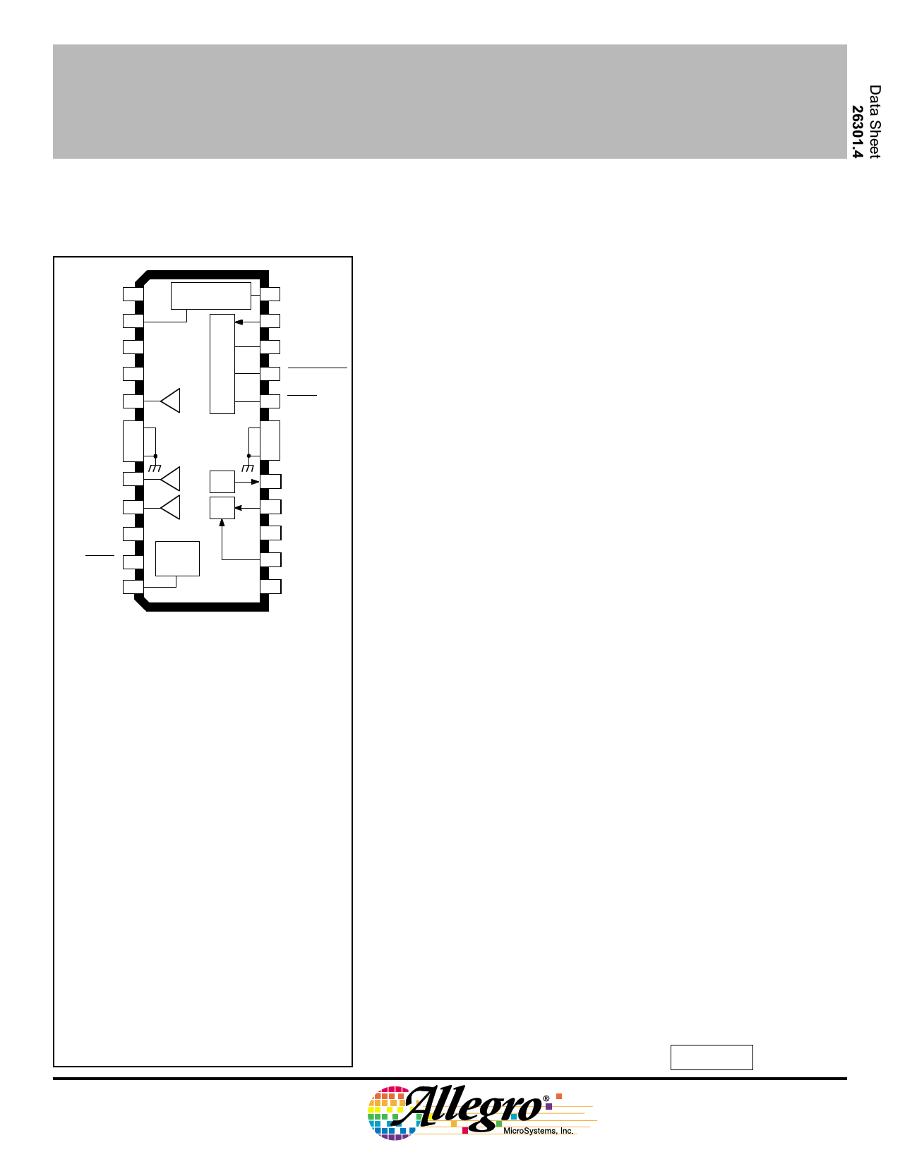
1
V BB
COMMUTATION
DELAY
C D2 2
C WD 3
CST 4
24 C D1
23 DATA IN
22 CLOCK
21 CHIP SELECT
OUTA 5
GROUND 6
20 RESET
19 GROUND
GROUND 7
18 GROUND
OUTB 8
MUX
17 DATA OUT
OUTC 99
CENTERTAP 10
BRAKE 11
C RES 12
BOOST
CHARGE
PUMP
FLL 16 OSCILLATOR
VDD 15
LOGIC
SUPPLY
14 SECTOR
DATA
13 FILTER
Dwg. PP-040B
ABSOLUTE MAXIMUM RATINGS
at TA = +25°C
Load Supply Voltage, VBB . . . . . . . . . . 14 V
Output Current, IOUT . . . . . . . . . . . . ±1.25 A
Logic Supply Voltage, VDD . . . . . . . . . 6.0 V
Logic Input Voltage Range,
VIN . . . . . . . . . . . -0.3 V to VDD + 0.3 V
Package Power Dissipation, PD See Graph
Operating Temperature Range,
TA . . . . . . . . . . . . . . . . . . 0°C to +70°C
Junction Temperature, TJ . . . . . . . +150°C†
Storage Temperature Range,
TS . . . . . . . . . . . . . . . -55°C to +150°C
† Fault conditions that produce excessive junction
temperature will activate device thermal shutdown
circuitry. These conditions can be tolerated, but
should be avoided.
Output current rating may be restricted to a value
determined by system concerns and factors.
These include: system duty cycle and timing,
ambient temperature, and use of any heatsinking
and/or forced cooling. For reliable operation, the
specified maximum junction temperature should
not be exceeded.
The A8906CLB is a bidirectional three-phase brushless dc motor
controller/driver. The three half-bridge outputs are low on-resistance n-
channel DMOS devices capable of driving up to 1 A. The A8906CLB
provides complete, reliable, self-contained back-EMF sensing motor
startup and running algorithms. A programmable digital frequency-
locked loop speed control circuit together with the linear current control
circuitry provides precise motor speed regulation.
A serial port allows the user to program various features and
modes of operation, such as the speed control parameters, rotational
direction, startup current limit, sleep mode, diagnostic modes, and
others.
The A8906CLB is fabricated in Allegro’s BCD (Bipolar CMOS
DMOS) process, an advanced mixed-signal technology that combines
bipolar, analog and digital CMOS, and DMOS power devices. The
A8906CLB is provided in a 24-lead wide-body SOIC batwing package.
It provides for the smallest possible construction in surface-mount
applications.
PRELIMINARY INFORMATION
FEATURES
(Subject to change without notice)
s DMOS Outputs
March 1, 1999
s Low rDS(on)
s Startup Commutation Circuitry
s Back-EMF Commutation Circuitry
s Direction Control
s Serial Port Interface
s Frequency-Locked Loop Speed Control
s Sector Data Tachometer Signal Input
s Programmable Start-Up Current
s Diagnostics Mode
s Sleep Mode
s Linear Current Control
s Internal Current Sensing
s Dynamic Braking Through Serial Port
s Power-Down Dynamic Braking
s System Diagnostics Data Out
s Data Out Ported in Real Time
s Internal Thermal Shutdown Circuitry
Always order by complete part number, e.g., A8906CLB .
1 page 
Term.
1
2
3
4
5
6-7
8
9
10
11
12
13
14
15
16
17
18-19
20
21
22
23
24
Terminal Name
LOAD SUPPLY
CD2
CWD
CST
OUTA
GROUND
OUTB
OUTC
CENTERTAP
BRAKE
CRES
FILTER
SECTOR DATA
LOGIC SUPPLY
OSCILLATOR
DATA OUT
GROUND
RESET
CHIP SELECT
CLOCK
DATA IN
CD1
8906
BIDIRECTIONAL
3-PHASE BRUSHLESS DC
MOTOR CONTROLLER/DRIVER
TERMINAL FUNCTIONS
Function
VBB; the 5 V or 12 V motor supply.
One of two capacitors used to generate the ideal commutation points from the
back-EMF zero crossing points.
Timing capacitor used by the watchdog circuit to disable the back-EMF compara-
tors during commutation transients, and to detect incorrect motor position.
Startup oscillator timing capacitor.
Power amplifier A output to motor.
Power and logic ground and thermal heat sink.
Power amplifier B output to motor.
Power amplifier C output to motor.
Motor centertap connection for back-EMF detection circuitry.
Active low turns ON all three sink drivers shorting the motor windings to ground.
External capacitor and resistor at BRAKE provide brake delay.
External reservoir capacitor used to hold charge to drive the source drivers’
gates. Also provides power for brake circuit.
Analog voltage input to control motor current. Also, compensation node for
internal speed control loop.
External tachometer input. Can use sector or index pulses from disk to provide
precise motor speed feedback to internal frequency-locked loop.
VDD; the 5 V logic supply.
Clock input for the speed reference counter. Typical max. frequency is 10 MHz.
Thermal shutdown indicator, FCOM, TACH, or SYNC signals available in real
time, controlled by 2-bit multiplexer in serial port.
Power and logic ground and thermal heat sink.
When pulled low forces the chip into sleep mode; clears all serial port bits.
Strobe input (active low) for data word.
Clock input for serial port.
Sequential data input for the serial port.
One of two capacitors used to generate the ideal commutation points from the
back-EMF zero crossing points.
5 Page 
8906
BIDIRECTIONAL
3-PHASE BRUSHLESS DC
MOTOR CONTROLLER/DRIVER
Dimensions in Inches
(for reference only)
24 13
0.0125
0.0091
0.2992
0.2914
0.020 1
0.013
2
3 0.6141
0.5985
0.0926
0.1043
0.0040 MIN.
0.491
0.394
0.050
0.016
0.050
BSC
NOTE 1
NOTE 3
0° TO 8°
Dwg. MA-008-25 in
Dimensions in Millimeters
(controlling dimensions)
24 13
0.32
0.23
7.60
7.40
0.51
0.33
1
2
3 15.60
15.20
2.65
2.35
0.10 MIN.
10.65
10.00
1.27
0.40
1.27
BSC
NOTE 1
NOTE 3
0° TO 8°
Dwg. MA-008-25A mm
NOTES: 1. Webbed lead frame. Leads 6, 7, 18, and 19 are internally one piece.
2. Lead spacing tolerance is non-cumulative.
3. Exact body and lead configuration at vendor’s option within limits shown.
11 Page | ||
| Páginas | Total 12 Páginas | |
| PDF Descargar | [ Datasheet 8906.PDF ] | |
Hoja de datos destacado
| Número de pieza | Descripción | Fabricantes |
| 890-19-024-10-000 | PCB connectors 2.54 mm Single row / double row Solder tail | Precid-Dip Durtal SA |
| 890-19-024-10-800 | PCB connectors 2.54 mm Single row / double row Solder tail | Precid-Dip Durtal SA |
| 890-19-024-10-802 | PCB connectors 2.54 mm Single row / double row Solder tail | Precid-Dip Durtal SA |
| 890-19-024-10-803 | PCB connectors 2.54 mm Single row / double row Solder tail | Precid-Dip Durtal SA |
| Número de pieza | Descripción | Fabricantes |
| SLA6805M | High Voltage 3 phase Motor Driver IC. |
Sanken |
| SDC1742 | 12- and 14-Bit Hybrid Synchro / Resolver-to-Digital Converters. |
Analog Devices |
|
DataSheet.es es una pagina web que funciona como un repositorio de manuales o hoja de datos de muchos de los productos más populares, |
| DataSheet.es | 2020 | Privacy Policy | Contacto | Buscar |