|
|
|
PDF 82C89 Data sheet ( Hoja de datos )
| Número de pieza | 82C89 | |
| Descripción | CMOS Bus Arbiter | |
| Fabricantes | Intersil Corporation | |
| Logotipo | ||
Hay una vista previa y un enlace de descarga de 82C89 (archivo pdf) en la parte inferior de esta página. Total 15 Páginas | ||
|
No Preview Available !
82C89
March 1997
CMOS Bus Arbiter
Features
Description
• Pin Compatible with Bipolar 8289
• Performance Compatible with:
- 80C86/80C88 . . . . . . . . . . . . . . . . . . . . . . . . . .(5/8MHz)
• Provides Multi-Master System Bus Control and
Arbitration
• Provides Simple Interface with 82C88/8288 Bus
Controller
• Synchronizes 80C86/8086, 80C88/8088 Processors
with Multi-Master Bus
• Bipolar Drive Capability
• Four Operating Modes for Flexible System Configura-
tion
• Low Power Operation
- ICCSB . . . . . . . . . . . . . . . . . . . . . . . . . . . . 10µA (Max)
- ICCOP . . . . . . . . . . . . . . . . . . . . . . . . .1mA/MHz (Max)
• Operating Temperature Ranges
- C82C89 . . . . . . . . . . . . . . . . . . . . . . . . . .0oC to +70oC
- I82C89 . . . . . . . . . . . . . . . . . . . . . . . . . -40oC to +85oC
- M82C89 . . . . . . . . . . . . . . . . . . . . . . . -55oC to +125oC
The Intersil 82C89 Bus Arbiter is manufactured using a self-
aligned silicon gate CMOS process (Scaled SAJI IV). This cir-
cuit, along with the 82C88 bus controller, provides full bus arbi-
tration and control for multi-processor systems. The 82C89 is
typically used in medium to large 80C86 or 80C88 systems
where access to the bus by several processors must be coordi-
nated. The 82C89 also provides high output current and capac-
itive drive to eliminate the need for additional bus buffering.
Static CMOS circuit design insures low operating power. The
advanced Intersil SAJI CMOS process results in perfor-
mance equal to or greater than existing equivalent products
at a significant power savings.
Ordering Information
PART NUMBER
CP82C89
IP82C89
CS82C89
IS82C89
CD82C89
ID82C89
MD82C89/B
5962-8552801RA
MR82C89/B
5962-85528012A
PACKAGE
20 Ld PDIP
20 Ld PLCC
20 Ld
CERDIP
SMD#
20 Pad
CLCC
SMD#
TEMPERATURE
RANGE
0oC to +70oC
-40oC to +85oC
0oC to +70oC
-40oC to +85oC
0oC to +70oC
-40oC to +85oC
-55oC to +125oC
PKG.
NO.
E20.3
E20.3
N20.35
N20.35
F20.3
F20.3
F20.3
F20.3
-55oC to +125oC J20.A
J20.A
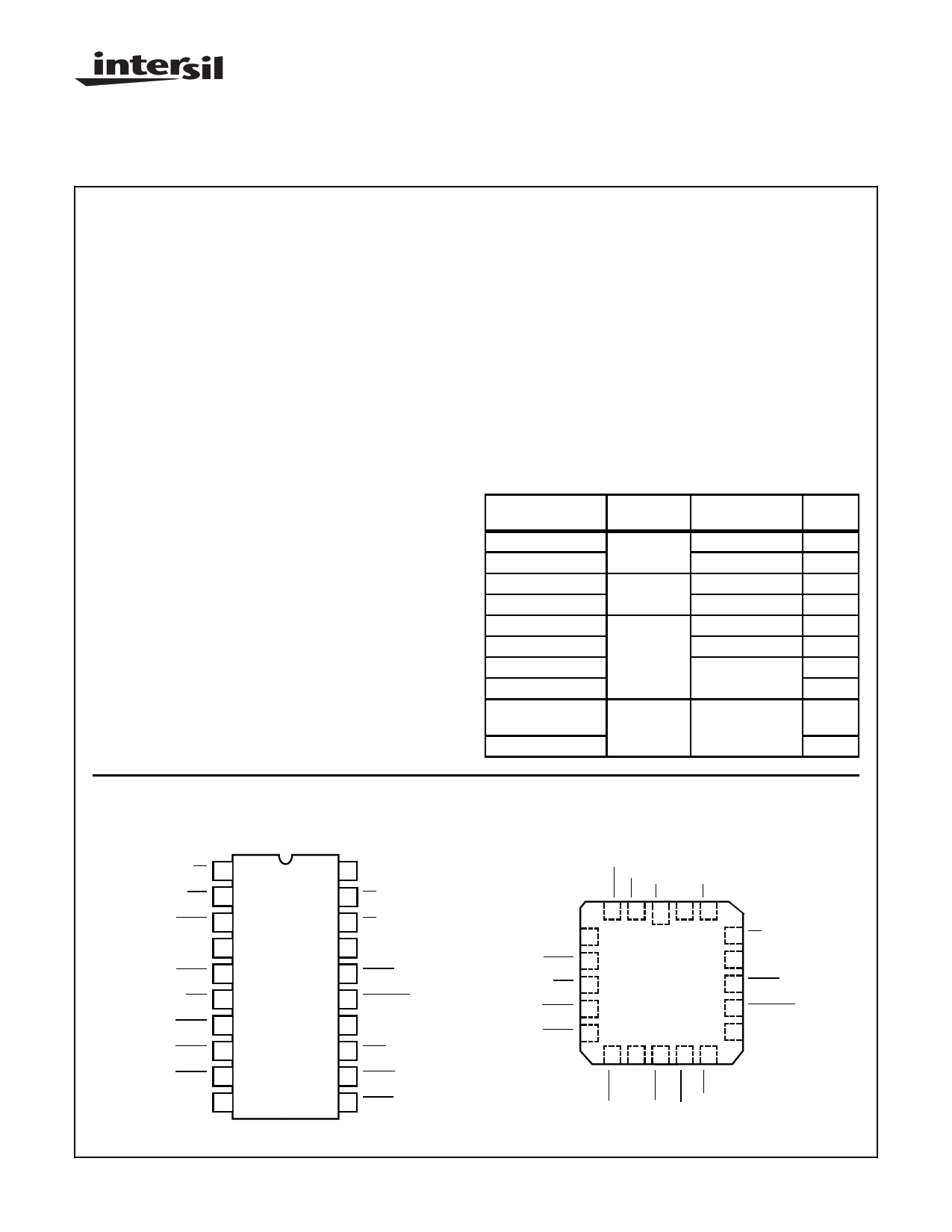
Pinouts
82C89 (CERDIP)
TOP VIEW
S2 1
IOB 2
SYSB/RESB 3
RESB 4
BCLK 5
INIT 6
BREQ 7
BPRO 8
BPRN 9
GND 10
20 VCC
19 S1
18 S0
17 CLK
16 LOCK
15 CRQLCK
14 ANYRQST
13 AEN
12 CBRQ
11 BUSY
82C89 (PLCC, CLCC)
TOP VIEW
3 2 1 20 19
RESB 4
BCLK 5
INIT 6
18 S0
17 CLK
16 LOCK
BREQ 7
BPRO 8
15 CRQLCK
14 ANYRQST
9 10 11 12 13
CAUTION: These devices are sensitive to electrostatic discharge; follow proper IC Handling Procedures.
http://www.intersil.com or 407-727-9207 | Copyright © Intersil Corporation 1999
4-343
File Number 2980.1
1 page 
82C89
Serial Priority Resolving
The serial priority resolving technique eliminates the need
for the priority encoder-decoder arrangement by daisychain-
ing the bus arbiters together, connecting the higher priority
bus arbiter’s BPRO (Bus Priority Out) output to the BPRN of
the next lower priority. See Figure 3.
BUS
ARBITER
1
BPRN
BPRO
BPRN
BUS
ARBITER
2
BPRO
BPRN
BUS
ARBITER BPRO
3
BPRN
BUS
ARBITER BPRO
4
techniques. It allows for many arbiters to be present on the
bus while not requiring too much logic to implement.
82C89 Modes Of Operation
There are two types of processors for which the 82C89 will
provide support: An Input/Output processor (i.e. an NMOS
8089 IOP) and the 80C86, 80C88. Consequently, there are
two basic operating modes in the 82C89 bus arbiter. One,
the IOB (I/O Peripheral Bus) mode, permits the processor
access to both an I/O Peripheral Bus and a multi-master sys-
tem bus. The second, the RESB (Resident Bus mode), per-
mits the processor to communicate over both a Resident
Bus and a multi-master system bus. An I/O Peripheral Bus is
a bus where all devices on that bus, including memory, are
treated as I/O devices and are addressed by I/O commands.
All memory commands are directed to another bus, the
multi-master system bus. A Resident Bus can issue both
memory and I/O commands, but it is a distinct and separate
bus from the multi-master system bus. The distinction is that
the Resident Bus has only one master, providing full avail-
ability and being dedicated to that one master.
••
••
CBRQ BUSY
•
•
FIGURE 3. SERIAL PRIORITY RESOLVING
NOTE: The number of arbiters that may be daisy-chained together
in the serial priority resolving scheme is a function of BCLK and the
propagation delay from arbiter to arbiter. Normally, at 10MHz only 3
arbiters may be daisychained.
Rotating Priority Resolving
The rotating priority resolving technique is similar to that of
the parallel priority resolving technique except that priority is
dynamically re-assigned. The priority encoder is replaced by
a more complex circuit which rotates priority between
requesting arbiters thus allowing each arbiter an equal
chance to use the multi-master system bus, over time.
Which Priority Resolving Technique To Use
There are advantages and disadvantages for each of the
techniques described above. The rotating priority resolving
technique requires substantial external logic to implement
while the serial technique uses no external logic but can
accommodate only a limited number of bus arbiters before the
daisy-chain propagation delay exceeds the multimaster’s sys-
tem bus clock (BCLK). The parallel priority resolving tech-
nique is in general a good compromise between the other two
The IOB strapping option configures the 82C89 Bus Arbiter
into the IOB mode and the strapping option RESB config-
ures it into the RESB mode. It might be noted at this point
that if both strapping options are strapped false, the arbiter
interfaces the processor to a multi-master system bus only
(see Figure 4). With both options strapped true, the arbiter
interfaces the processor to a multi-master system bus, a
Resident Bus, and an I/O Bus.
In the IOB mode, the processor communicates and controls
a host of peripherals over the Peripheral Bus. When the I/O
Processor needs to communicate with system memory, it
does so over the system memory bus. Figure 5 shows a pos-
sible I/O Processor system configuration.
The 80C86 and 80C88 processors can communicate with a
Resident Bus and a multi-master system bus. Two bus con-
trollers and only one Bus Arbiter would be needed in such a
configuration as shown in Figure 6. In such a system config-
uration the processor would have access to memory and
peripherals of both busses. Memory mapping techniques are
applied to select which bus is to be accessed. The
SYSB/RESB input on the arbiter serves to instruct the arbi-
ter as to whether or not the system bus is to be accessed.
The signal connected to SYSB/RESB also enables or dis-
ables commands from one of the bus controllers. A sum-
mary of the modes that the 82C89 has, along with its
response to its status lines inputs, is shown in Table 1.
4-347
5 Page 
82C89
AC Electrical Specifications
VCC = 5.0V ± 10%; GND = 0V:
TA
TA
TA
=
=
=
0oC to +70oC (C82C89);
-40oC to +85oC (I82C89);
-55oC to +125oC (M82C89)
SYMBOL
PARAMETER
MIN
MAX
UNIT
TEST CONDITIONS
(1) TCLCL
CLK Cycle Period
125 - ns Note 3
(2) TCLCH
CLK Low Time
55 - ns Note 3
(3) TCHCL
CLK High Time
35 - ns Note 3
(4) TSVCH
Status Active Setup
65 TCLCL-10 ns Note 3
(5) TSHCL
Status Inactive Setup
50 TCLCL-10 ns Note 3
(6) THVCH
Status Inactive Hold
10 - ns Note 3
(7) THVCL
Status Active Hold
10 - ns Note 3
(8) TBYSBL
BUSY↓↑ Setup to BCLK↓
20 - ns Note 3
(9) TCBSBL
CBRQ↓↑ Setup to BCLK↓
20 - ns Note 3
(10) TBLBL
BCLK Cycle Time
100 - ns Note 3
(11) TBHCL
BCLK High Time
30 0.65 ns Note 3
(TBLBL)
(12) TCLLL1
LOCK Inactive Hold
10 - ns Note 3
(13) TCLLL2
LOCK Active Setup
40 - ns Note 3
(14) TPNBL
BPRN↓↑ to BCLK Setup Time
20 - ns Note 3
(15) TCLSR1
SYSB/RESB Setup
0 - ns Note 3
(16) TCLSR2
SYSB/RESB Hold
30 - ns Note 3
(17) TIVIH
Initialization Pulse Width
675 - ns Note 3
(18) TBLBRL
BCLK to BREQ Delay↓↑
- 35 ns Note 3
(19) TBLPOH
BCLK to BPRO↓↑
- 35 ns Note 1 and 3
(20) TPNPO
BPRN↓↑ to BPRO↓↑ Delay
- 22 ns Note 1 and 3
(21) TBLBYL
BCLK to BUSY Low
- 60 ns Note 3
(22) TBLBYH
BCLK to BUSY Float
- 35 ns Note 2 and 3
(23) TCLAEH
CLK to AEN High
- 65 ns Note 3
(24) TBLAEL
BCLK to AEN Low
- 40 ns Note 3
(25) TBLCBL
BCLK to CBRQ Low
- 60 ns Note 3
(26) TBLCBH
BCLK to CBRQ Float
- 40 ns Note 2 and 3
(27) TOLOH
Output Rise Time
- 20 ns From 0.8V to 2.0V, Note 4
(28) TOHOL
Output Fall Time
- 12 ns From 2.0V to 0.8V, Note 4
(29) TILIH
Input Rise Time
- 20 ns From 0.8V to 2.0V
(30) TIHIL
Input Fall Time
- 20 ns From 2.0V to 0.8V
NOTES:
1. BCLK generates the first BPRO wherein subsequent BPRO changes lower in the chain are generated through BPRON.
2. Measured at 0.5V above GND.
3. All AC parameters tested as per AC test load circuits. Input rise and fall times are driven at 1ns/V.
4. Except BUSY and CBRQ
4-353
11 Page | ||
| Páginas | Total 15 Páginas | |
| PDF Descargar | [ Datasheet 82C89.PDF ] | |
Hoja de datos destacado
| Número de pieza | Descripción | Fabricantes |
| 82C802G | System / Power Management Controller | Opti |
| 82C802GP | System / Power Management Controller | Opti |
| 82C814 | Docking Station Controller Preliminary Data Book | Opti |
| 82C82 | CMOS Octal Latching Bus Driver | Intersil Corporation |
| Número de pieza | Descripción | Fabricantes |
| SLA6805M | High Voltage 3 phase Motor Driver IC. |
Sanken |
| SDC1742 | 12- and 14-Bit Hybrid Synchro / Resolver-to-Digital Converters. |
Analog Devices |
|
DataSheet.es es una pagina web que funciona como un repositorio de manuales o hoja de datos de muchos de los productos más populares, |
| DataSheet.es | 2020 | Privacy Policy | Contacto | Buscar |