|
|
|
PDF M74HCT648 Data sheet ( Hoja de datos )
| Número de pieza | M74HCT648 | |
| Descripción | HCT646 OCTAL BUS TRANSCEIVER/REGISTER 3-STATE HCT648 OCTAL BUS TRANSCEIVER/REGISTER 3-STATE / INV. | |
| Fabricantes | ST Microelectronics | |
| Logotipo | ||
Hay una vista previa y un enlace de descarga de M74HCT648 (archivo pdf) en la parte inferior de esta página. Total 12 Páginas | ||
|
No Preview Available !
M74HCT646
M74HCT648
HCT646 OCTAL BUS TRANSCEIVER/REGISTER (3-STATE)
HCT648 OCTAL BUS TRANSCEIVER/REGISTER (3-STATE, INV.)
. HIGH SPEED
fMAX = 60 MHz (TYP.) AT VCC = 5 V
. LOW POWER DISSIPATION
ICC = 4 µA (MAX.) AT TA = 25 °C
. COMPATIBLE WITH TTL OUTPUTS
VIH = 2V (MIN.) VIL = 0.8V (MAX)
. OUTPUT DRIVE CAPABILITY
15 LSTTL LOADS
. SYMMETRICAL OUTPUT IMPEDANCE
IOH= IOL = 6 mA (MIN.)
. BALANCED PROPAGATION DELAYS
tPLH = tPHL
. PIN AND FUNCTION COMPATIBLE
WITH 54/74LS646/648
B1R
(Plastic Package)
M1R
(Micro Package)
ORDER CODES :
M74HCTXXXM1R M74HCTXXXB1R
DESCRIPTION
The M74HCT646/648 are high speed CMOS
OCTAL BUS TRANSCEIVERS AND REGISTERS,
(3-STATE) fabricated in silicon gate C2MOS tech-
nology. They have the same high speed
performance of LSTTL combined with true CMOS
low power consumption. These devices consist of
bus transceiver circuits with 3-state output, D-type
flip-flops, and control circuitry arranged for multi-
plexed transmission of data directly from the input
bus or from the internal registers. Data on the A or
B bus will be clocked into the registers on the low-
to-high transition of the appropriate clock pin (Clock
AB - or Clock BA). Enable (G) and direction (DIR)
pins are provided to control the transceiver function-
s. In the transceiver mode, data present at the
high-impedance port may be stored in either register
or in both. The select controls (Select AB select BA)
can multiplex stored and real-time (transparent
mode) data. The direction control determines which
bus will receive data when enable G is active (low).
In the isolation mode (enable G high), ”A” data may
be stored in one register and/or ”B” data may be
stored in the other register. When an output function
is disabled, the input function is still enabled and
may be used to store and transmit data. Only one
of the two buses, A or B, may be driven at a time.
All inputs are equipped with protection circuits
against static discharge and transient excess volt-
age.This integrated circuit has input and output
characteristics that are fully compatible with 54/74
LSTTL logic families. M74HCT devices are de-
signed to directly interface HSC2MOS systems with
TTL and NMOS components. They are also plug in
replacements for LSTTL devices giving a reduction
of power consumption.
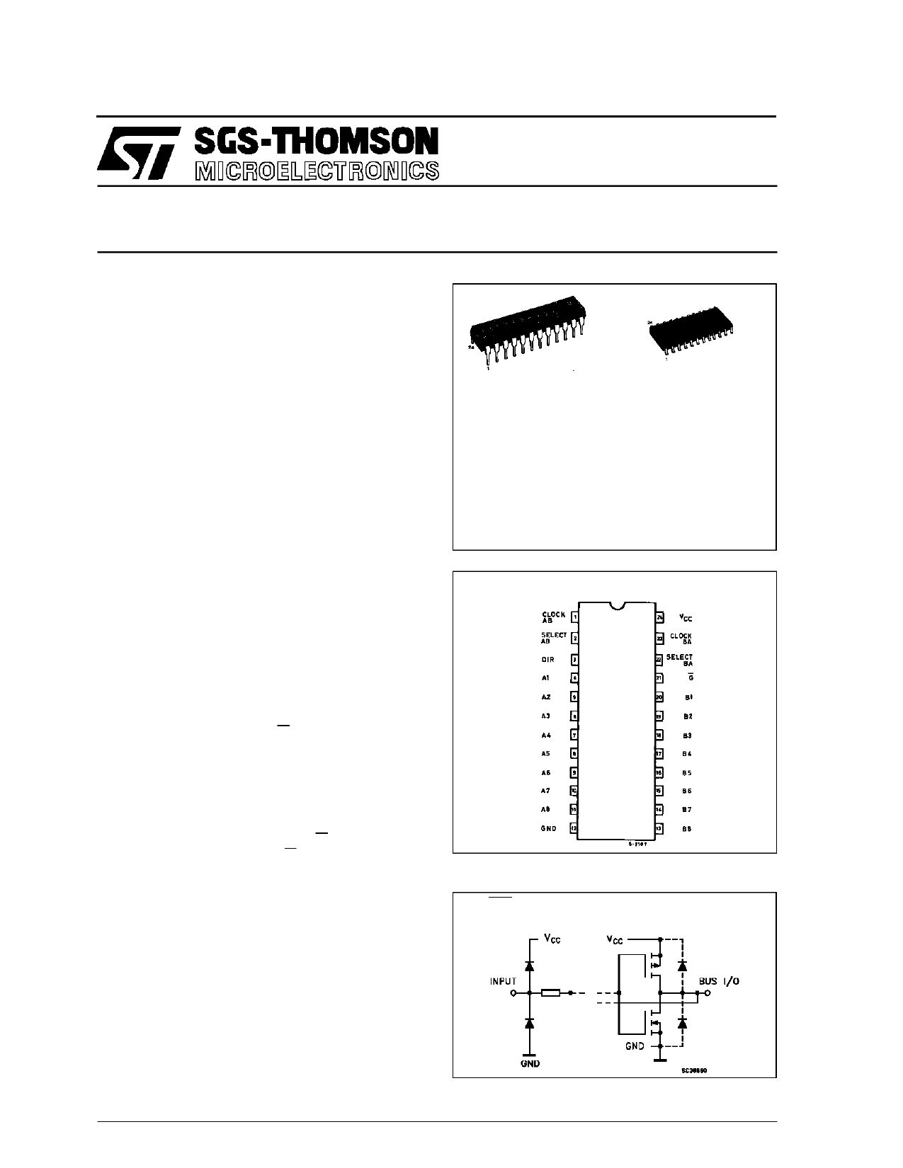
PIN CONNECTIONS (top view)
INPUT AND OUTPUT EQUIVALENT CIRCUIT
GAB, GAB, CAB,
SAB, SBA, CBA
A, B
October 1993
1/12
1 page 
M74HCT646/648
ABSOLUTE MAXIMUM RATINGS
Symbol
Parameter
Value
Unit
VCC Supply Voltage
-0.5 to +7
V
VI DC Input Voltage
-0.5 to VCC + 0.5
V
VO DC Output Voltage
-0.5 to VCC + 0.5
V
IIK DC Input Diode Current
IOK DC Output Diode Current
IO DC Output Source Sink Current Per Output Pin
± 20 mA
± 20 mA
± 35 mA
ICC or IGND DC VCC or Ground Current
± 70 mA
PD Power Dissipation
500 (*)
mW
Tstg Storage Temperature
-65 to +150
oC
TL Lead Temperature (10 sec)
300 oC
Absolute Maximum Ratings are those values beyond which damage to the device may occur. Functional operation under these condition isnotimplied.
(*) 500 mW: ≅ 65 oC derate to 300 mW by 10mW/oC: 65 oC to 85 oC
RECOMMENDED OPERATING CONDITIONS
Symbol
VCC
VI
VO
Top
tr, tf
Parameter
Supply Voltage
Input Voltage
Output Voltage
Operating Temperature
Input Rise and Fall Time (VCC = 4.5 to 5.5V)
Value
4.5 to 5.5
0 to VCC
0 to VCC
-40 to +85
0 to 500
Unit
V
V
V
oC
ns
5/12
5 Page 
DIM.
A
a1
a2
b
b1
C
c1
D
E
e
e3
F
L
S
MIN.
0.10
0.35
0.23
15.20
10.00
7.40
0.50
SO24 MECHANICAL DATA
mm
TYP.
0.50
1.27
13.97
MAX.
2.65
0.20
2.45
0.49
0.32
MIN.
0.004
0.013
0.009
45° (typ.)
15.60
0.598
10.65
0.393
7.60 0.291
1.27 0.19
8° (max.)
L
M74HCT646/648
inch
TYP.
0.020
0.05
0.55
MAX.
0.104
0.007
0.096
0.019
0.012
0.614
0.420
0.299
0.050
c1
b
24
e3
D
e
13
s
E
1 12
11/12
11 Page | ||
| Páginas | Total 12 Páginas | |
| PDF Descargar | [ Datasheet M74HCT648.PDF ] | |
Hoja de datos destacado
| Número de pieza | Descripción | Fabricantes |
| M74HCT640 | OCTAL BUS TRANSCEIVER3-STATE: HCT245 NON INVERTING HCT640 INVERTING / HCT643 INVERTING/NON INVERTING | ST Microelectronics |
| M74HCT643 | OCTAL BUS TRANSCEIVER3-STATE: HCT245 NON INVERTING HCT640 INVERTING / HCT643 INVERTING/NON INVERTING | ST Microelectronics |
| M74HCT646 | HCT646 OCTAL BUS TRANSCEIVER/REGISTER 3-STATE HCT648 OCTAL BUS TRANSCEIVER/REGISTER 3-STATE / INV. | ST Microelectronics |
| M74HCT648 | HCT646 OCTAL BUS TRANSCEIVER/REGISTER 3-STATE HCT648 OCTAL BUS TRANSCEIVER/REGISTER 3-STATE / INV. | ST Microelectronics |
| Número de pieza | Descripción | Fabricantes |
| SLA6805M | High Voltage 3 phase Motor Driver IC. |
Sanken |
| SDC1742 | 12- and 14-Bit Hybrid Synchro / Resolver-to-Digital Converters. |
Analog Devices |
|
DataSheet.es es una pagina web que funciona como un repositorio de manuales o hoja de datos de muchos de los productos más populares, |
| DataSheet.es | 2020 | Privacy Policy | Contacto | Buscar |