|
|
|
PDF M66290AFP Data sheet ( Hoja de datos )
| Número de pieza | M66290AFP | |
| Descripción | USB DEVICE CONTROLLER | |
| Fabricantes | Mitsubishi | |
| Logotipo | ||
Hay una vista previa y un enlace de descarga de M66290AFP (archivo pdf) en la parte inferior de esta página. Total 30 Páginas | ||
|
No Preview Available !
Ver.1.0 Oct. 27, 2000
MITSUBISHI <DIGITAL ASSP>
M66290AGP/FP
USB DEVICE CONTROLLER
DESCRIPTION
The M66290A is a general purpose USB (Univ ersal Serial
Bus) dev ice controller compatible with the USB
specif ication v ersion 1.1 and corresponds to f ull speed
transf er. Built-in transceiv er circuits meet all transf er ty pe
which is def ined in USB.
M66290A has FIFO of 3k By tes f or data transf er and can
set 6 endpoints (maximum).
Each endpoint can be set programmable of its transf er
condition, so can correspond to each dev ice class transf er
sy stem of USB.
FEATURES
· USB specif ication 1.1 compliant
· Built-in USB transceiv er circuit
· Supports Full Speed (12 Mbps) transmission
· Supports all f our USB transf er t y pe :
· Control transf er
· Bulk transf er
· Isochronous transf er
· Interrupt transf er
· Built-in FIFO (3 KBy tes) f or Endpoint
· Up to 6 endpoint (EP0 to EP5) selectable
· Data transf er condition selectable f or each
Endpoints (EP1 to EP5)
· Data transf er t y pe
(Bulk, Isochronous and Interrupt)
· Transf er direction (IN/OUT)
· Buf f er size of FIFO (maximum 1024 By tes)
· Double (Toggle) buf f er conf iguration
· Continuous transf er mode
(Buf f ering up to 1 KBy teX2)
· Max packet size
· Supports 4 input clock f requencies
· Input clock : 6/12/24/48 MHz
· Built-in PLL which has an oscillation buf f er
and outputs at 48 MHz
· Supports both 8-bit and 16-bit DMA transf ers
· 16-bit CPU bus interf ace
· 3.3V single power source
· Built-in JTAG
APPLICATION
· Printer , Scanner , DSC , DVC
· PC camera , Multimedia speaker , Terminal adapter etc.
· Support all PC peripheral using Full Speed USB
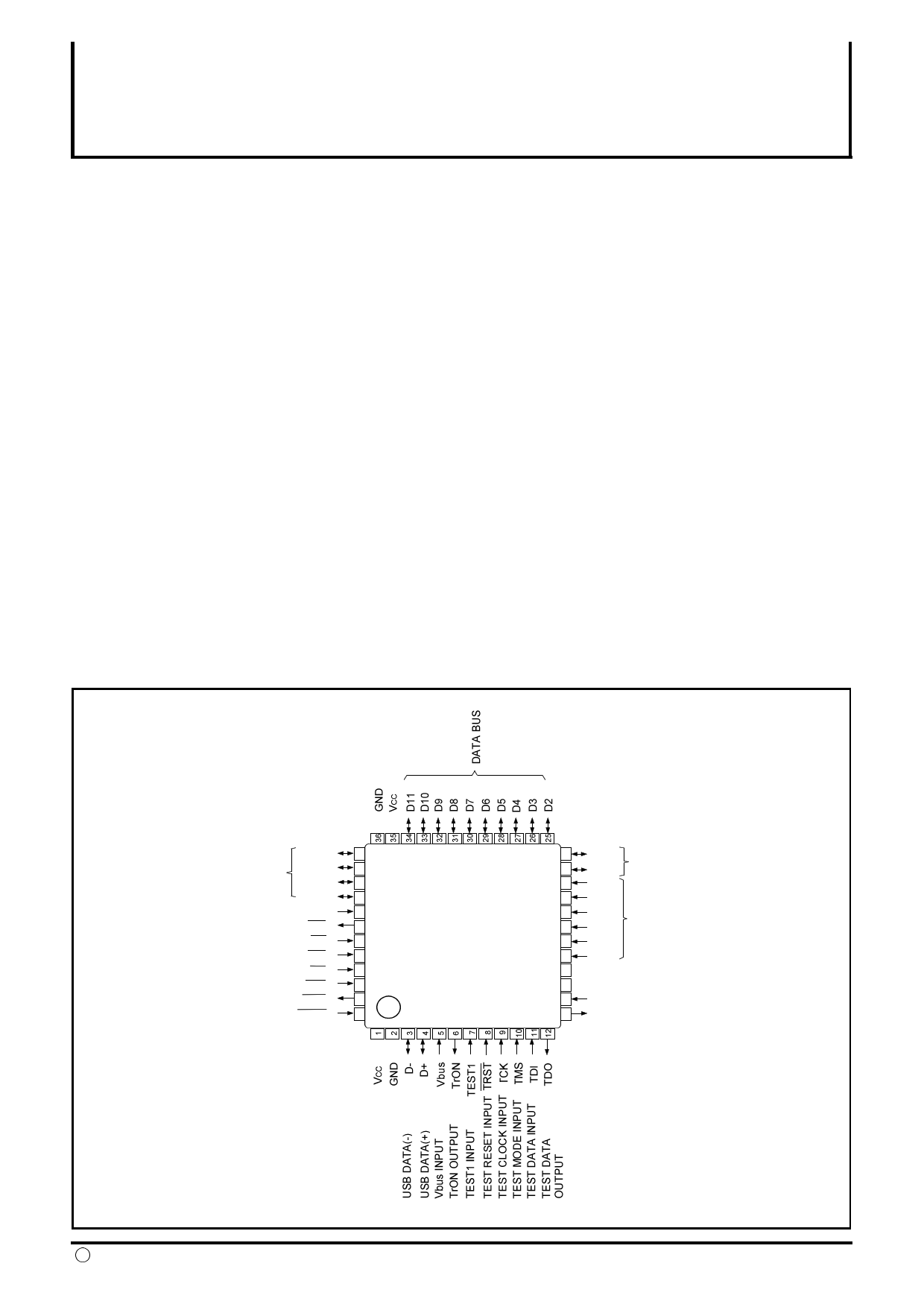
PIN CONFIGURATION
(TOP VIEW)
DATA BUS
TEST2 INPUT
INT E RRUPT
READ STROBE
WRITE STROBE
CHIP SELECT
RESET
DMA REQUEST
DMA ACKNOWLEDGE
D12
D13
D14
D15
TEST2
INT
RD
WR
CS
RST
Dreq
Dac k
37
38
39
40
41
42
43
44
45
46
47
48
M66290AGP
OR
M66290AFP
24 D1
23 D0
DATA BUS
22 A6
21 A5
20 A4
19 A3
ADDRESS BUS
18 A2
17 A1
16 VCC
15 GND
14 Xin OSCILLAT OR INPUT
13 Xout OSCILLAT OR OUTPUT
Outline
M66290AGP:48P6Q-A(LQFP)
M66290AFP:48P6X-A(TQFP)
c MITSUBISHI ELECTRIC CORPORATION
1
1 page 
MITSUBISHI <DIGITAL ASSP>
M66290AGP/FP
CONTROL REGISTER TABLE
Below is the table of registers of M66290A.
Bit width of all register is 16bits.
In reset item, "H/W" shows the reset status
by external RST input, "S/W" shows reset
status by USBE register, and "USB"
USB DEVICE CONTROLLER
shows the reset status by receiv ing USB reset.
" - " shows that the prev ious status is kept.
Write into reserv ed address is inhibited.
Address
00h
02h
04h
06h
08h
0Ah
0Ch to 0Eh
10h
12h
14h
16h
18h
1Ah
1Ch
1Eh
20h
22h
24h
26h
28h
2Ah
2Ch
2Eh
30h
32h
34h
36h
38h to 3Eh
40h
42h
44h
46h
48h
4Ah
4Ch
4Eh to 5Eh
60h
62h
64h
66h
68h
6Ah
6Ch
6Eh
70h
Name
USB Operation Enable Register
Remote Wake-up Register
Sequence Bit Clear Register
Reserved
USB_Address Register
IsochronousStatus Register
Reserved
Interrupt Enable Register0
Interrupt Enable Register1
Interrupt Enable Register2
Interrupt Enable Register3
Interrupt Status Register0
Interrupt Status Register1
Interrupt Status Register2
Interrupt Status Register3
Request Register
Value Register
Index Register
Length Register
Control Transfer Control Register
EP0 Packet Size Register
Auto-response Control Register
Reserved
EP0_FIFO Selection Register
EP0_FIFO Control Register
EP0_FIFO Data Register
EP0 Continuous transmit Data Length
Reserved
CPU_FIFO Selection Register
CPU_FIFO Control Register
CPU_FIFO Data Register
Reserved
DMA_FIFO Selection Register
DMA_FIFO Control Register
DMA_FIFO Data Register
Reserved
EP1 Configuration Register0
EP1 Configuration Register1
EP2 Configuration Register0
EP2 Configuration Register1
EP3 Configuration Register0
EP3 Configuration Register1
EP4 Configuration Register0
EP4 Configuration Register1
EP5 Configuration Register0
R/W
R/W
R/W
R/W
R
R/W (note 2)
R/W
R/W
R/W
R/W
R/W (note 2)
R
R/W
R/W
R
R
R
R
R/W
R/W
R/W
R/W
R/W (note 2)
R/W
R/W
R/W
R/W (note 2)
R/W
R/W
R/W (note 2)
R/W
R/W
R/W
R/W
R/W
R/W
R/W
R/W
R/W
R/W
H/W
0000h
0000h
0000h
0000h
0000h
0000h
0000h
0000h
0000h
0000h
0000h
0000h
0000h
0000h
0000h
0000h
0000h
0000h
0008h
0000h
0000h
0800h
xxxx
0000h
0000h
0800h
xxxx
0000h
0800h
xxxx
0000h
0040h
0000h
0040h
0000h
0040h
0000h
0040h
0000h
S/W
-
0000h
0000h
0000h
0000h
0000h
0000h
0000h
0000h
0000h
0000h
0000h
0000h
-
-
-
-
-
-
-
-
-
-
-
-
-
-
-
-
-
-
-
-
-
-
-
-
-
-
USB
-
-
-
0000h
-
-
-
-
-
Note 2
-
-
-
-
-
-
-
-
-
-
-
-
-
-
-
-
-
-
-
-
-
-
-
-
-
-
-
-
-
note 1 : Detail description is mentioned later.
note 2 : Some are read only.
5
5 Page 
MITSUBISHI <DIGITAL ASSP>
M66290AGP/FP
USB DEVICE CONTROLLER
Each of "Set Address" and "Set Conf iguration" execution
detects the dev ice state shif t by analy zing the dev ice
request in control transf er.
Each of these f our f actors can be set of its interrupt to
enable or disable by setting the corresponded bit of
interrupt enable register 0.
For example by using this interrupt, when USB bus reset
is detected, a step to USB bus is av ailable and when
suspend is detected, a step to shif t dev ice to low power
consumption.
Control transfer stage transition interrupt (CTRT)
M66290A manages the sequence of control transf er
by H/W.
Each stage of c ontrol transf er, such as setup stage,
data stage, and status stage can be known to ref er to
the "Interrupt Status Register 0".
Control transf er stage transition interrupt is occurred
when the control transf er stage is shif ted.
There are f iv e f actors, that is, setup stage end,
control write transf er stage shif t, control read transf er
stage shif t, control transf er end, and control transf er
sequence error.
Except f or setup stage, Each of these f our f actors can
be set of its interrupt to enable or disable by setting the
corresponded bit of interrupt enable register 0.
As to control transf er sequence error which can be
recognized by H/W, ref er to "Control transf er stage
shif t" in the item of "(3) Control transf er/enumeration"
in the latter part.
Endpoint buffer empty/size-over interrupt (BEMP)
Interrupt f actor is dif f erent by transf er direction of
endpoint.
1. In case of transf er direction is IN
In each endpoint, interrupt occurs when transmission
ended of all data which is stored in the buf f er.
By this interrupt, when endpoint is set to double buf f er,
end of data transmission of all data of the buf f er can
be known.
And also can know the end of data transmission of
control read transf er in endpoint 0 (EP0).
2. In case of transf er direction is OUT
In each endpoint, interrupt occurs in data packet
receiv e when receiv ed packet which exceeds the
maximum packet size.
By ref er to EPB_EMP_OVR[5:0] of interrupt status
register, it can be known which endpoint occurred the
interrupt.
Endpoint buffer not ready interrupt (INTN)
When the buf f er is in not ready state to IN/OUT token
of each endpoint, interrupt occurs at the timing of token
packet receiv e end.
By ref er to EPB_NRDY[5:0] of interrupt status register 1,
it can be known which endpoint occurred the interrupt.
If endpoint is set to isochronous transf er, when ov er-run/
under-run error is occurred, interrupt occurs at the timing
of token packet receiv e end.
And if it is set to isochronous (OUT), if receiv ed data
has
error such as CRC error, interrupt occurs at the timing of
transaction end.
The v ariety of error in isochronous transf er is known to
ref er "Isochronous Status Register".
Endpoint buffer ready interrupt (INTR)
Interrupt occurs when the buf f er of each endpoint
became ready (read/write is av ailable).
It can be known which endpoint occurred the interrupt
to ref er EPB_RDY [5:0] of interrupt status register 1.
According to the endpoint and its access mode, the
f actor of interrupt is dif f erent as f ollows.
1. In case of EP0
Interrupt occurs when receiv e (OUT) buf f er of endpoint
0 became ready .
If it is set to control write continuous receiv e mode,
when continuous receiv e of 255 by tes ended or when
receiv ed short packet, interrupt occurs.
Interrupt is not occurred ev en if the transmit buf f er
became ready .
2. In case of EP1 to EP5, when CPU access
Interrupt occurs when the buf f er of each endpoint
became ready .
3. In case of EP1 to EP5, when DMA access
If the transf er direction is set to OUT, interrupt occurs
when receiv ed short data packet and then ended DMA
transf er.
Interrupt is not occurred if the transf er direction is set
to IN.
11
11 Page | ||
| Páginas | Total 30 Páginas | |
| PDF Descargar | [ Datasheet M66290AFP.PDF ] | |
Hoja de datos destacado
| Número de pieza | Descripción | Fabricantes |
| M66290AFP | USB DEVICE CONTROLLER | Mitsubishi |
| Número de pieza | Descripción | Fabricantes |
| SLA6805M | High Voltage 3 phase Motor Driver IC. |
Sanken |
| SDC1742 | 12- and 14-Bit Hybrid Synchro / Resolver-to-Digital Converters. |
Analog Devices |
|
DataSheet.es es una pagina web que funciona como un repositorio de manuales o hoja de datos de muchos de los productos más populares, |
| DataSheet.es | 2020 | Privacy Policy | Contacto | Buscar |