|
|
|
PDF M63013FP Data sheet ( Hoja de datos )
| Número de pieza | M63013FP | |
| Descripción | SPINDLE MOTOR AND 4CH ACTUATOR DRIVER | |
| Fabricantes | Mitsubishi | |
| Logotipo | ||
Hay una vista previa y un enlace de descarga de M63013FP (archivo pdf) en la parte inferior de esta página. Total 17 Páginas | ||
|
No Preview Available !
Preliminary
MITSUBISHI SEMICONDUCTORS
M63013FP
SPINDLE MOTOR AND 4CH ACTUATOR DRIVER
[FEATURES]
This IC is 1 chip driver IC for spindle motor and 4 channel
actuators. All of the motor and actuator of optical disk drive
system (CD-ROM etc.) can be drived by only this IC.
This IC has current control drive system for Focus, Tracking,
Spindle and Slide channel drive, also has a direct PWM
control system for Spindle and Slide channels drive due to
reducing IC power dissipation.
This IC has three voltage supply terminals (for Spindle,
Slide/Loading and Focus/Tracking) , and these voltage
supply can be set separately.
Further more this IC has an operational amplifier for Slide
input, FG amplifier, thermal shut down circuit, standby circuit,
channel select function, reverse rotation detect circuit and
Short braking select.
[APPLICATION]
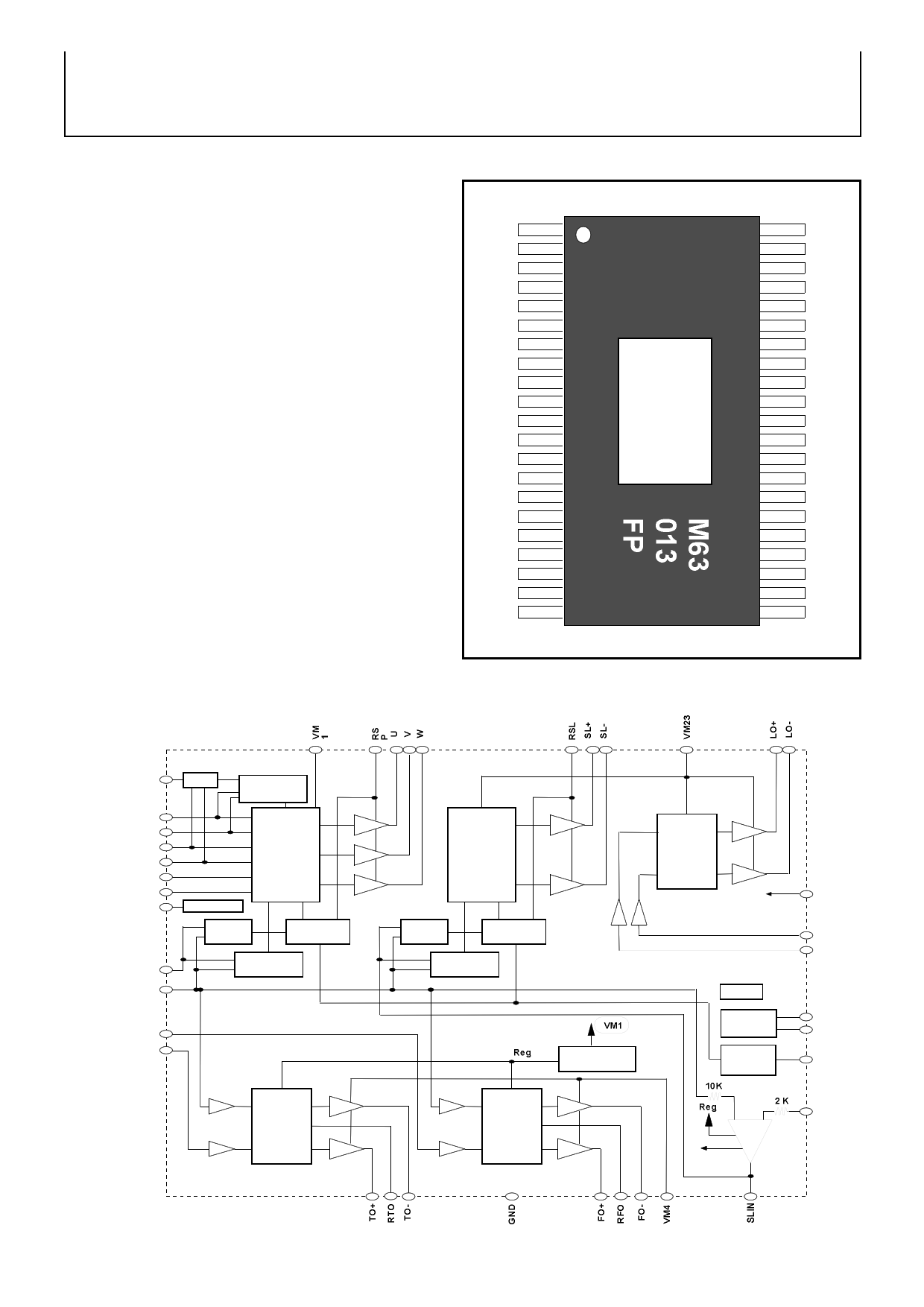
PIN CONFIGURATION
(Top View)
LOIN+
MU1
MU2
VM23
LO+
LO-
GND
RSL
SL+
SL-
GND
W
V
U
RSP
HW-
HW+
HV-
HV+
HU-
HU+
1
2
3
4
5
6
7
8
9
10
11
12
13
14
15
16
17
18
19
20
21
42 LOIN-
41 RFO
40 RTO
39 5VCC
38 VM4
37 TO-
36 TO+
35 FO+
34 FO-
33 GND
32 SLIN
31 OPIN-
30 OSC
29 GND
28 FOIN
27 TOIN
26 SPIN
25 REF
24 FG
23 HB
22 VM1
Package outline : 42 PIN POWER SSOP (42P9R-B)
CD-ROM, DVD, DVD-ROM, DVD-RAM ,Optical disc related system,etc
[BLOCK DIAGRAM]
FG
HU+
HU-
HV+
HV-
HW+
HW-
HB
SPIN
REF
ss
FG Reverse
Detect
Spindle
Hall Bias
CTL
amp.
Current
comp.
Direction
comp.
TOIN
FOIN
s
Slide
CTL
amp.
Current
comp.
Direction
comp.
Regulator
Focus
s
Tracking
s
s
Loading
5Vpower
supply
5VCC
LOIN+
LOIN-
TSD
BIAS
Frequency
generator
MU1
MU2
OSC
+-
5VCC
OPIN-
( 1 / 17)
REV990607
1 page 
Preliminary
MITSUBISHI SEMICONDUCTORS
M63013FP
SPINDLE MOTOR AND 4CH ACTUATOR DRIVER
[ELECTRICAL CHARACTERISTICS]
Spindle
(Ta=25ºC, 5VCC=VM4=5V,VM1=VM23=12V unless otherwise noted.)
LIMITS
SYMBOL
PARAMETER
CONDITIONS
Vdyc1
Dynamic range of output
Io=0.5 [A]
Vdead1-
SPIN<REF
Vdead1+ Control voltage dead zone 1
REF<SPIN
[REVERSE]
[FORWARD]
MIN
10.3
-80
0
TYP
10.8
-40
+40
MAX
0
+80
Unit
V
mV
mV
Vin1
Control voltage input range 1 SPIN
0 5V
Gvo1
Control gain 1
Vlim1F Control limit 1F
Gio1=Gvo1/ Rs [A/V]
0.85 1.0 1.15 V/V
Ilim1F=Vlim1F/ Rs [A]
[FORWARD]
0.4
0.5
0.6 V
Vlim1R Control limit 1R
Ilim1R=Vlim1R/ Rs [A]
[REVERSE]
0.27
0.34 0.41
V
VHcom Hall sensor amp.
Hu+,Hu-,Hv+,Hv-,Hw+ ,Hw-
1.3
3.7 V
common mode input range
VHmin
Hu+,Hu-,Hv+,Hv-,Hw+ ,Hw-
Hall sensor amp.input signal level
60
mVp-p
VHB
IHB
HB output voltage
HB terminal sink current
at Load current (IHB)=10mA
MU1=MU2=0V or MU1=MU2=5V or
MU1=5V/MU2=0V
0.6 0.85 1.2 V
30 mA
Slide
(Ta=25ºC, 5VCC=VM4=5V,VM1=VM23=12V unless otherwise noted.)
LIMITS
SYMBOL
PARAMETER
Vdyc2
Dynamic range of output
Vdead2-
Vdead2+ Control voltage dead zone 2
CONDITIONS
Io=0.5 [A]
at VM23=5[V]
at VM23=12[V]
SLIN < REF
REF < SLIN
MIN
3.3
10.3
-80
0
TYP
3.8
10.8
-40
+40
MAX
Unit
V
0 mV
+80 mV
Vin2
Control voltage input range 2 SLIN
0 5V
Gvo2
Control gain 2
Gio2=Gvo2/ Rs [A/V]
0.85 1.0 1.15 V/V
Vlim2
Control limit 2
Ilim2=Vlim2/ Rs [A]
0.43 0.5 0.58 V
Tdon
Output turn-on delay
1.0 2.0 µsec
Tdoff Output turn-off delay
3.5 7.0 µsec
Tdsw Output switching delay
5.0 10.0 µsec
Ileak
Output leak current
MU1=MU2=5v,MU1=MU2=0v
( 5 / 17)
-100
100 µA
REV990607
5 Page 
Preliminary
MITSUBISHI SEMICONDUCTORS
M63013FP
SPINDLE MOTOR AND 4CH ACTUATOR DRIVER
FOCUS / TRACKING channel
The focus and tracking channel is the current feedback control
drive of MITSUBISHI original.The focus and tracking is the same
composition.
The relationship between the differential voltage between FOIN
and REF and the output current is shown in right Figure.
The voltage gain is 0.4 [V/V].Therefore, the current gain is
0.8[A/V] in case of the sensing resistor is 0.5 ohm.
The maximum range of output swing is limited around 7.5 volts,in
case of VM4 is above 10 volts.
FOIN
REF
2.5R
2.5R
VM4
R
R
R
FO-
R Rs
R RFO
Coil
R
FO+
+
Coil
current [A]
IL=Vrs / Rs IL
0
FOIN– REF (V)
FO-
Rs
RFO
VM4
2
Coil
Gio=1.0A/V
at Rs=0.33 ohm
-
Output
voltage [V]
Vrs Vrs=(RFO–[FO-])
=0.4 x (FOIN–REF)
FO+
+
Coil
-
Vcoil
FOIN– REF (V)
FO+
(11 / 17)
RFO
FO-
Rs
REV990607
11 Page | ||
| Páginas | Total 17 Páginas | |
| PDF Descargar | [ Datasheet M63013FP.PDF ] | |
Hoja de datos destacado
| Número de pieza | Descripción | Fabricantes |
| M63013FP | SPINDLE MOTOR AND 4CH ACTUATOR DRIVER | Mitsubishi |
| Número de pieza | Descripción | Fabricantes |
| SLA6805M | High Voltage 3 phase Motor Driver IC. |
Sanken |
| SDC1742 | 12- and 14-Bit Hybrid Synchro / Resolver-to-Digital Converters. |
Analog Devices |
|
DataSheet.es es una pagina web que funciona como un repositorio de manuales o hoja de datos de muchos de los productos más populares, |
| DataSheet.es | 2020 | Privacy Policy | Contacto | Buscar |