|
|
|
PDF M62256FP Data sheet ( Hoja de datos )
| Número de pieza | M62256FP | |
| Descripción | Single chip battery charger control IC | |
| Fabricantes | Mitsubishi | |
| Logotipo | ||
Hay una vista previa y un enlace de descarga de M62256FP (archivo pdf) en la parte inferior de esta página. Total 9 Páginas | ||
|
No Preview Available !
Mitsubishi Integrated Circuit <Digital/Analog Interface>
M62256FP
Single chip battery charger control IC
Outline
M62256FP is a semiconductor integrated circuit designed to control
the battery charger. This IC controls not only all the time sequence
needed for battery charging,but also gives full support for detection
of battery temperature,protection over current and voltage,and safety
timer,etc. It is also a simple matter to charge Ni-Cd,Ni-MH batteries
by adding a small peripheral components to this IC.
This IC has a feedback controlling of the charge current and the output
voltage.
Features
• Designed for low voltage(3V)operation.
• Built-in CR oscillator is used for internal logic.
• Built-in initialization timer and safety timer enable -∆V error
detection and over-charging.
• Built-in D/A converter and shift-resister circuits to maintain the
peak voltage of battery.
• Built-in Main output SW and discharge drive circuits.
• Built-in LED drive circuits for displaying the status of the power
supply and charging/discharging.
Pin Configuration(Top view)
C1 1
E1 2
C2 3
E2 4
C3 5
E3 6
Rc 7
Cc 8
Dchg IN 9
Dchg OUT 10
Chg SW 11
GND2 12
Batt SW 13
Dchg SW 14
Adpt SW 15
Test1 16
Test2 17
N.C 18
36 Vref1
35 ISET2
34 ISET1
33 OCSET
32 PCS OUT
31 PCS IN
30 CP1
29 IDET
28 Vcc
27 GND1
26 CP2
25 VDET
24 P.C
23 Batt T
22 Vref2
21 Batt -
20 Batt +
19 N.C
• Built-in System Reset circuit for detecting the power supply
voltage.
36P2R
• Built-in temperature detection circuit for the Ni-MH battery
• Built-in voltage and current control circuit which enables
feedback to the primary side of the SMPS.
Uses
• Built-in protective functions including detection of over-voltage
in charge mode and over-current in adapter mode, and others.
General electronic battery charger for VCR and
camera in one unit, handheld telephones, etc.
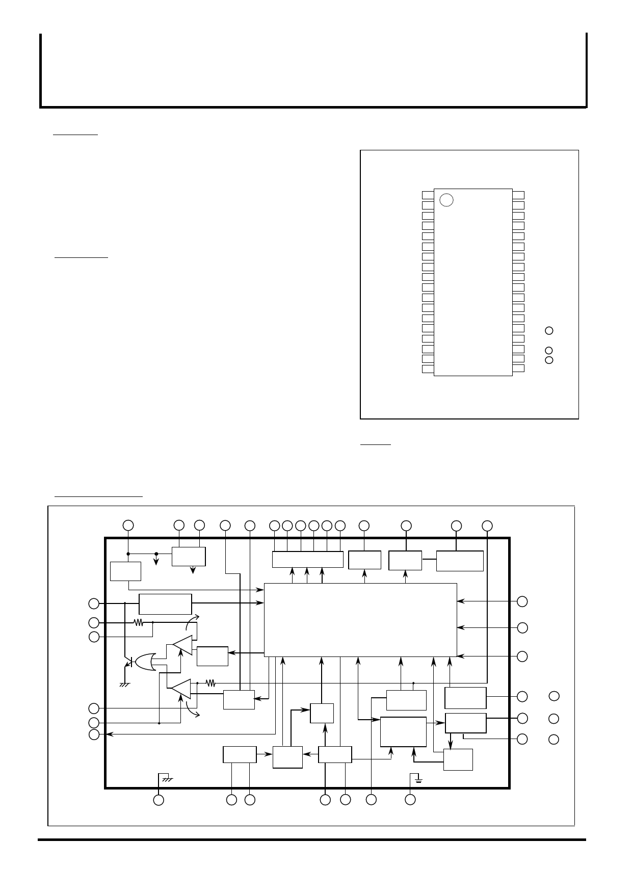
Block diagram
Vcc Vref2 Vref1 Iset2 Iset1 C1 C2 C3 E1E2 E3 Chg SW Dchg OUT Dchg IN I DET
28
22 36 35 34
13 524 6
11
10
9 29
P.C 24
VDET 25
CP2 26
Stabl'd
Pwr. Sup.
System
Reset ckt.
to internal
circuit
to internal
circuit
Detect un-
plugged PS cord
Voltage
control
OP Amp.
+
– Voltage
set-up ckt.
LED driver
Output SW Discharge
driver
driver
Discharge
current control
Control logic
14 Dchg SW
13 Batt SW
15 Adpt SW
CP1 30
PSC IN 31
PSC OUT 32
+
– Current
set-up ckt.
Current
control
OP Amp.
Safety
timer
Oscillator
Clock
gen. ckt.
Test ckt.
Over-current
det. ckt.
-∆V error det.
prev. logic
Battery temp
det. ckt.
Batt. voltage
det. ckt.
-∆V det.
logic
23 Batt T
20 Batt +
21 Batt –
12
GND2
(A.GND)
78
Rc Cc
16 17
33
27
Test1 Test2 OCSET GND
(P.GND)
1 page 
Mitsubishi Integrated Circuit <Digital/Analog Interface>
M62256FP
Single chip battery charger control IC
Internal Voltage Set-up
Items
Set-up output voltage at Adpt mode
Set-up output voltage at charge mode
Set-up output voltage when
over-current is detected
ISET1set-up voltage
ISET2set-up voltage
OCSET set-up voltage
Over-voltage set-up voltage
-∆V detection voltage1
-∆V detection voltage2
Voltage at the end of discharge
Temperature detection set-up voltage1
Temperature detection set-up voltage2
Over-heating detection set-up voltage
Symbols
VAdpt
VCHG
Conditions
Standard
Min Typ Max
Unit
820 864 910 mV
1.19 1.26 1.33 V
V DOWN
478 504 530 mV
V ISET1
V ISET2
VOCSET
VOVP
V -∆V-1
V -∆V-2
VCHGON
VTTH1
V TTH2
VO/H
When quick charging
When trickle charging
When adapter mode
within Initialization timer
after initialization timer has passed
Temperature at the start of charging
Temperature at the start of recharging
Charge stop temperature
123
11.4
208
9.0
0.6
60
4.7
0.92
1.06
0.81
130
12.0
220
9.5
1.0
100
5.0
0.97
1.12
0.86
137
12.6
232
10
1.4
140
5.3
1.02
1.18
0.91
mV
mV
mV
V
V
mV
V
V
V
V
Items
Symbols
Conditions
Standard
Min Typ Max
Unit
Oscillation frequency
fosc Rc=30KÉ∂ , Cc=2200pF
9.22 10.24 11.26 KHz
Initialization timer1
Tm1
Battery voltage<5V
18.0 20.0 22.0 min
Initialization timer2
Initialization timer3
Undetected time for -É¢V
Safety timer1
Tm2
Tm3
TNDET
Tms1
5V≤Battery voltage<6.5V
Battery voltage≥6.5V
when quick charging
4.5 5.0 5.5 min
2.7 3.0 3.3 min
2.7 3.0 3.3 min
2.7 3.0 3.3 hr
Safety timer2
Tms2
when trickle charging
21.6 24 26.4 hr
Over-current detection time
TOC
9.0 10.0 11.0 sec
Note: The time given to each timer is when the oscillation frequency of 10.24KHz is used.
Recommended Operating Range
Power supply voltage (Vcc) …………………… 3~15V
Charge current (See Note1)
Preliminary charge ……………………… 50~200mA
Quick charge …………………………… 0.8~2A
Trickle charge …………………………… 80~200mA
Discharge current (See Note1) ………………… 300~500mA
LED drive current (See Note2) ………………… 115mA
Note1. The charging current must be set according to the battery specifications.
The currents used for quick charge and trickle charge are detemined by the voltage
of the terminals Iset1 and Iset2 and current sense resistor R4 (Application in page 9).
Note2. The LED drive current is calculated by the following equation.
I LED
•=•
200mV
RL
(A)
5 Page | ||
| Páginas | Total 9 Páginas | |
| PDF Descargar | [ Datasheet M62256FP.PDF ] | |
Hoja de datos destacado
| Número de pieza | Descripción | Fabricantes |
| M62256FP | Single chip battery charger control IC | Mitsubishi |
| Número de pieza | Descripción | Fabricantes |
| SLA6805M | High Voltage 3 phase Motor Driver IC. |
Sanken |
| SDC1742 | 12- and 14-Bit Hybrid Synchro / Resolver-to-Digital Converters. |
Analog Devices |
|
DataSheet.es es una pagina web que funciona como un repositorio de manuales o hoja de datos de muchos de los productos más populares, |
| DataSheet.es | 2020 | Privacy Policy | Contacto | Buscar |