|
|
|
PDF LC5852N Data sheet ( Hoja de datos )
| Número de pieza | LC5852N | |
| Descripción | Four-Bit Single-Chip Microcontroller with On-Chip LCD Drivers for Small-Scale Control in Medium-Speed Applications | |
| Fabricantes | Sanyo | |
| Logotipo | ||
Hay una vista previa y un enlace de descarga de LC5852N (archivo pdf) en la parte inferior de esta página. Total 29 Páginas | ||
|
No Preview Available !
Ordering number : EN 4365B
CMOS LSI
LC5852N
Four-Bit Single-Chip Microcontroller with
On-Chip LCD Drivers for Small-Scale Control in
Medium-Speed Applications
Overview
The LC5852N is a high-performance four-bit single-chip
built-in LCD driver microprocessor that provides a variety
of attractive features including low-voltage operation and
low power dissipation. The LC5852N was developed as an
upwardly compatible version of the LC5851N and
provides a ROM capacity increased from 1024 to 2048 15-
bit words and a RAM capacity increased from 64 × 4 bits
to 128 × 4 bits.
Applications
• System control and LCD display in cameras, radios and
similar products
• System control and LCD display in miniature electronic
test equipment and consumer health maintenance
products
• The LC5852N is optimal for end products with LCD
displays and, in particular, for battery operated products.
Features
The LC5852N is an upwardly compatible version of the
LC5851N and, as such, has the following features.
• Extremely broad allowable operating ranges
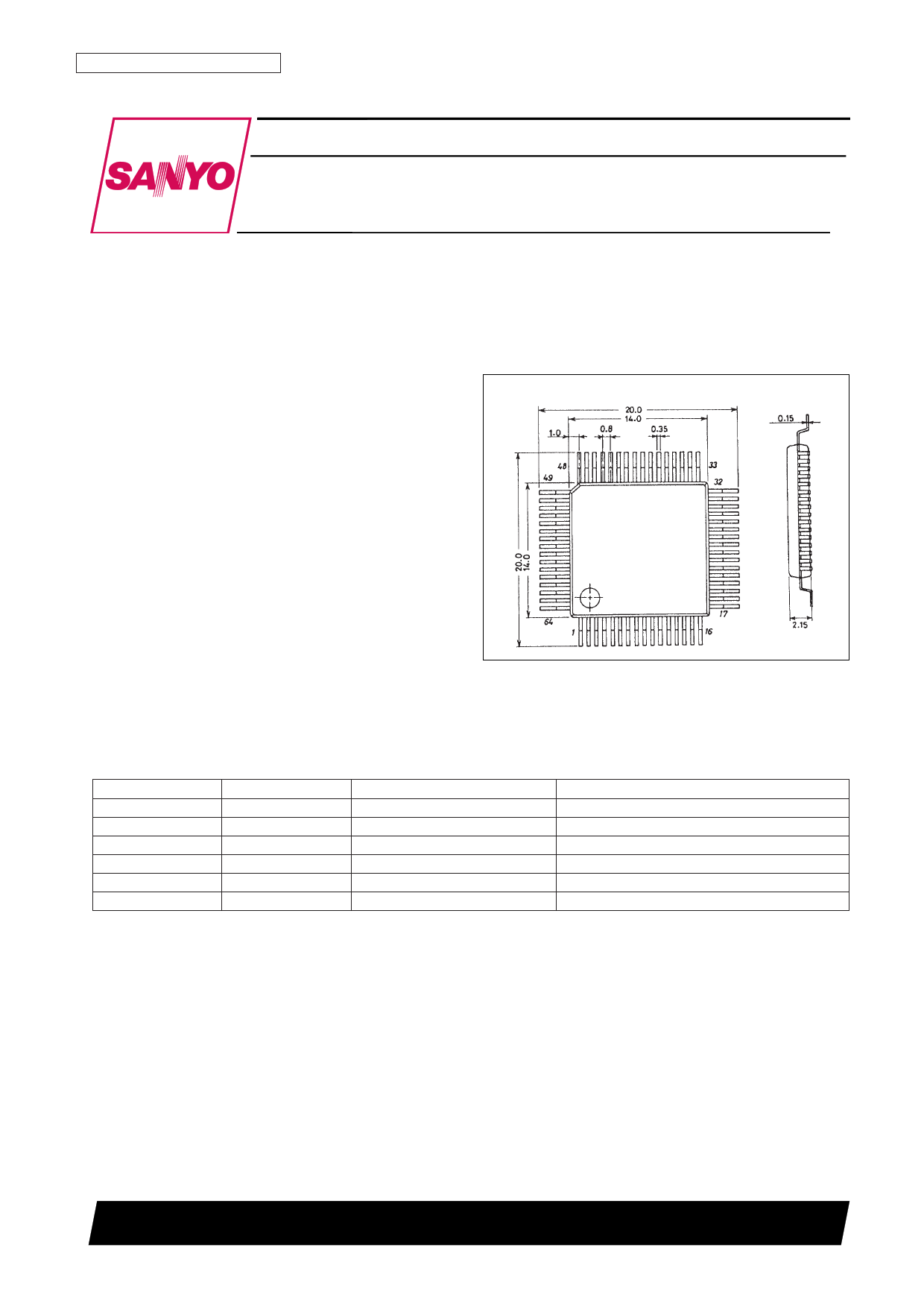
Package Dimensions
unit: mm
3057-QIP64A
[LC5852N]
SANYO: QIP64A
Power supply option
Cycle time
Power supply voltage range
Note
EXT-V
EXT-V
EXT-V
EXT-V
Li
Ag
10 µs
20 µs
61 µs
122 µs, 244 µs
122 µs, 244 µs
122 µs, 244 µs
VSS2 = –4.0 to –5.5 V
VSS2 = –4.0 to –5.5 V
VSS2 = –2.3 to –5.5 V
VSS2 = –2.0 to –5.5 V
VSS2 = –2.6 to –3.6 V*
VSS1 = –1.3 to –1.65 V
When using an 800 kHz ceramic resonator
When using a 400 kHz ceramic resonator
When using a 65 kHz crystal oscillator
When using a 32 kHz crystal oscillator
When using a 32 kHz crystal oscillator
When using a 32 kHz crystal oscillator
Note: * When the backup flag is set, the BAK pin is shorted to VSS2. (See the user’s manual for details.)
• Low current drain
— Ceramic oscillator (CF):
— Crystal oscillator (Xtal):
— Crystal oscillator (Xtal):
400 kHz (5.0 V)
32 kHz (1.5 V, Ag specifications)
32 kHz (3.0 V, Li specifications)
HALT mode (typical)
150 µA
2.0 µA (for LCD biases other than 1/3)
3.5 µA (for an LCD bias of 1/3)
1.0 µA (for LCD biases other than 1/3)
5.0 µA (for an LCD bias of 1/3)
SANYO Electric Co.,Ltd. Semiconductor Bussiness Headquarters
TOKYO OFFICE Tokyo Bldg., 1-10, 1 Chome, Ueno, Taito-ku, TOKYO, 110-8534 JAPAN
O3095HA (OT)/91994TH (OT) No. 4365-1/29
1 page 
LC5852N
Pin Functions
Pin
VDD
BAK
VSS1
VSS2
VSS3
QIP-64
I/O Pin No.
Function
Option
At reset
— 40 Power supply plus side
LSI internal logic block minus power supply
— 41 In Li specification products, connect a capacitor between BAK and VDD
to prevent incorrect operation.
Backup flag set
Backup flag cleared
(depending on the
power supply option)
Power supply minus side
• External component connections differ depending on mask options
—
—
—
42
43
39
and other factors.
In products for Ag use, connect VSS1 to the power supply minus side.
In other products, connect VSS2 to the power supply minus side.
• The pins other than the minus pin are used for the LCD driver power
• Ag specifications
• Li specifications
• EXT-V
specifications
supply.
CUP1
CUP2
—
—
4
5
Connections for the LCD drive voltage boost (cut) capacitor.
OSC-IN
Input
8
Used for real-time clock and the system clock.
OSC-OUT Output
9
• Crystal oscillator
use (XT option)
• Ceramic resonator
use (CF option)
The CF option can
only be specified for
EXT-V specification
products.
10P
—
—
Connected to OSC-IN or OSC-OUT and used for the oscillator phase
compensation capacitor. Can only be used in the chip product.
S1
S2
S3
S4
Input
7
6
47
46
Dedicated input port
• Includes either a ø10 (32 ms), ø8 (8 ms), or ø2 (2 ms) chattering
exclusion circuit (PLA mask option).
* These values are for the case where a 32.768 kHz crystal is used.
• Pull-down resistors are built in.
Inclusion
(or exclusion) of a
low level hold
transistor
The pull-down
resistor transistor is
on.
M1
M2
M3
M4
Input
62
63
64
1
Dedicated input port
• Input connections for acquiring data to internal RAM
• Pull-down resistors are built in.
Inclusion
(or exclusion) of a
low level hold
transistor
The pull-down
resistor transistor is
on.
I/O A1
I/O A2
I/O A3
I/O A4
I/O B1
I/O B2
I/O B3
I/O B4
P1
P2
P3
P4
ALM
LIGHT
48 I/O port
I/O
49 • Input connections for acquiring data to internal RAM
50 • Output connections for data output from internal RAM
51 • The input or output state can be switched by two instructions.
Input mode
52 I/O port
I/O
53 • Input connections for acquiring data to internal RAM
54 • Output connections for data output from internal RAM
55 • The input or output state can be switched by two instructions.
Input mode
58
Output
59
60
Output port
• Output connections for data output from internal RAM
61
Either a high- or
low-level output.
(Undefined)
Output
44
Dedicated output
This pin can output a signal modulated either at 4 kHz or 2 kHz, or at
4 kHz or 1 kHz under program control. Alternatively, an unmodulated
signal can be output.
* These values are for the case where a 32.768 kHz crystal is used.
• Modulated signals
(4 kHz, 2 kHz, or
unmodulated)
• Modulated signals
(4 kHz, 1 kHz, or
unmodulated)
Low-level output
Output
45
Dedicated output
This pin can drive a power transistor.
Low-level output
Continued on next page.
No. 4365-5/29
5 Page 
LC5852N
Mask Option Overview
1. Power supply specification selection
• Ag (Silver battery/1.5 V) specifications
• Li (Lithium battery/3.0 V) specifications
• EXT-V specifications (the operating voltage range depends on the oscillator used)
2. Oscillator selection
• Crystal oscillator (32.768 kHz)
• Crystal oscillator (65.536 kHz)
• Ceramic oscillator
3. LCD drive
• Static
• 1/2 bias—1/2 duty
• 1/2 bias—1/3 duty
• 1/2 bias—1/4 duty
• 1/3 bias—1/3 duty
• 1/3 bias—1/4 duty
Note: The LCD ports can all be used as general-purpose outputs. In this case, specify the “UNUSE” option.
6. LCD alternation frequency
• SLOW (OSC/2048)
• TYP (OSC/1024)
• FAST (OSC/512)
• STOP
5. S port low-level hold transistor
• Level hold transistor present
• No level hold transistor
6. M port low-level hold transistor
• Level hold transistor present
• No level hold transistor
7. S and M port chattering exclusion frequency
• SLOW (OSC/1024)
• TYP (OSC/256)
• FAST (OSC/64)
8. INT pin resistor selection and signal edge type selection
• Pull-up resistor (negative)
• Pull-down resistor (positive)
• Open (negative)
• Open (positive)
9. External reset
• RES pin
• Simultaneous input to S1 through S4
10. RES pin
• Pull-up resistor (low-level reset)
• Pull-down resistor (high-level reset)
• Open (low-level reset)
• Open (high-level reset)
11. Power-on reset function (internal reset)
• USE
• UNUSE
12. Timer input clock
• SLOW (OSC/512)
• FAST (OSC/8)
13. Alarm modulation base frequency
• SLOW (OSC/8, OSC/32)
• TYP (OSC/8, OSC/16)
14. Cycle time
• SLOW (OSC/8)
• FAST (OSC/4)
Note: Specify “SLOW” for this option if a ceramic oscillator is used.
No. 4365-11/29
11 Page | ||
| Páginas | Total 29 Páginas | |
| PDF Descargar | [ Datasheet LC5852N.PDF ] | |
Hoja de datos destacado
| Número de pieza | Descripción | Fabricantes |
| LC5852N | Four-Bit Single-Chip Microcontroller with On-Chip LCD Drivers for Small-Scale Control in Medium-Speed Applications | Sanyo |
| Número de pieza | Descripción | Fabricantes |
| SLA6805M | High Voltage 3 phase Motor Driver IC. |
Sanken |
| SDC1742 | 12- and 14-Bit Hybrid Synchro / Resolver-to-Digital Converters. |
Analog Devices |
|
DataSheet.es es una pagina web que funciona como un repositorio de manuales o hoja de datos de muchos de los productos más populares, |
| DataSheet.es | 2020 | Privacy Policy | Contacto | Buscar |