|
|
|
PDF LA4550 Data sheet ( Hoja de datos )
| Número de pieza | LA4550 | |
| Descripción | 2-Channel AF Power Amplifier | |
| Fabricantes | Sanyo | |
| Logotipo | ||
Hay una vista previa y un enlace de descarga de LA4550 (archivo pdf) en la parte inferior de esta página. Total 9 Páginas | ||
|
No Preview Available !
Ordering number:ENN1718B
Monolithic Linear IC
LA4550
2-Channel AF Power Amplifier
for Radio, Tape Recorder Use
Features
• Low quiescent current.
• On-chip 2 channels permitting use in stereo and bridge
amplifier applications.
• High output.
• Minimum number of external parts required.
(9 pcs. munimum)
• Good ripple rejection (at steady state).
• Soft tone at the output saturation mode.
• Good channel separation.
• Easy thermal design.
• Small pop noise at the time of power supply ON/OFF.
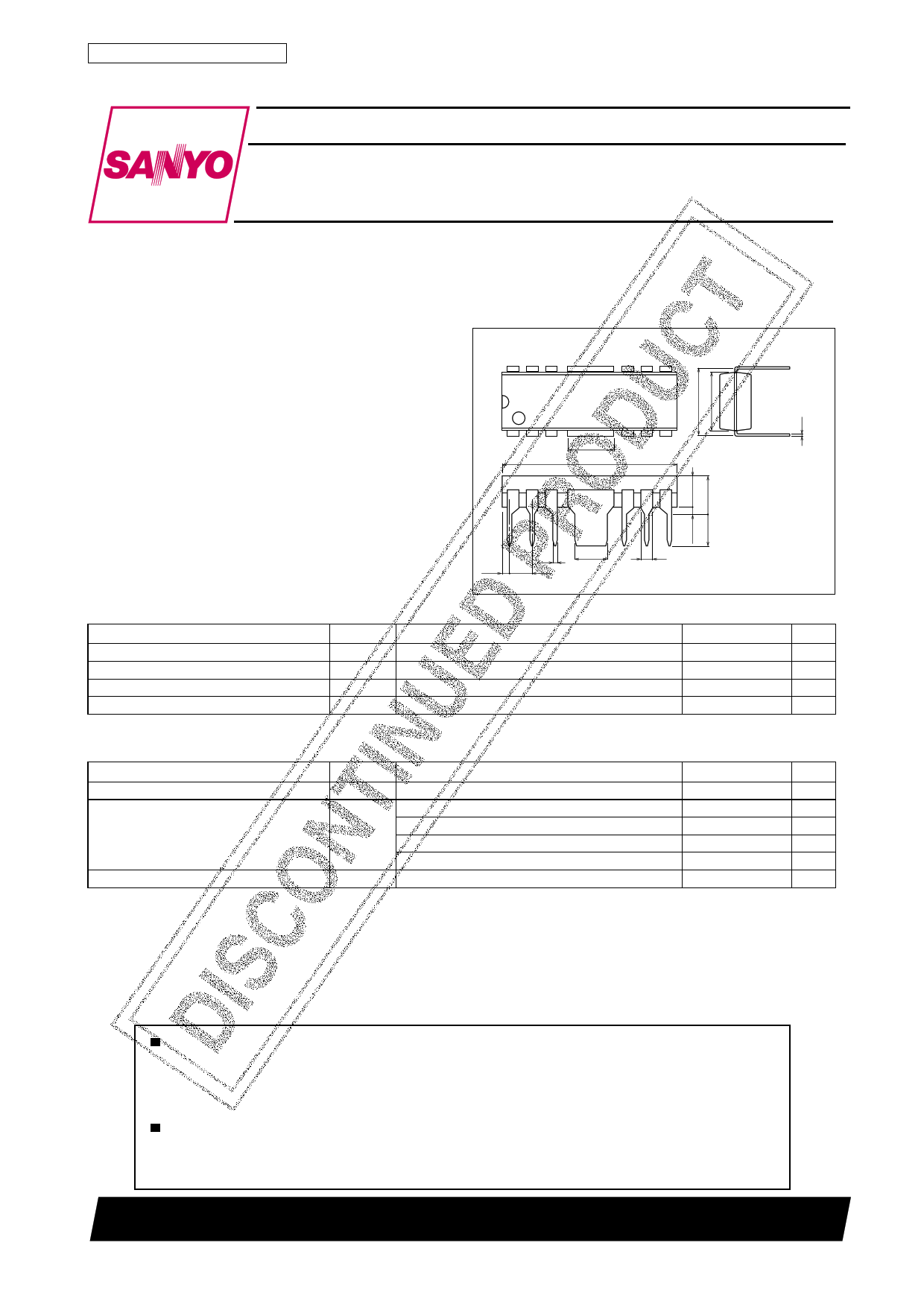
Package Dimensions
unit:mm
3022A-DIP12F
[LA4550]
12 7
1 5.12 6
19.4
Specifications
Absolute Maximum Ratings at Ta = 25˚C
Parameter
Symbol
Maximum supply voltage
Allowable power dissipation
Operating temperature
VCC max
Pd max*
Topr
Storage temperature
Tstg
* With recommended PCB (See sample printed circuit pattern.)
Operating Conditions at Ta = 25˚C
Parameter
Recommended supply voltage
Recommended load resistance
Operating voltage range
Symbol
VCC
RL
VCCop
Stereo 6V
BTL 6V
Stereo 9V
BTL 9V
0.5 3.6
0.81 2.54
Conditions
Conditions
1.3
SANYO : DIP12F
Ratings
13
4
–20 to +75
–55 to +150
Unit
V
W
˚C
˚C
Ratings
6, 9
2 to 8
4 to 8
4 to 8
8
3.6 to 12
Unit
V
Ω
Ω
Ω
Ω
V
Any and all SANYO products described or contained herein do not have specifications that can handle
applications that require extremely high levels of reliability, such as life-support systems, aircraft’s
control systems, or other applications whose failure can be reasonably expected to result in serious
physical and/or material damage. Consult with your SANYO representative nearest you before using
any SANYO products described or contained herein in such applications.
SANYO assumes no responsibility for equipment failures that result from using products at values that
exceed, even momentarily, rated values (such as maximum ratings, operating condition ranges,or other
parameters) listed in products specifications of any and all SANYO products described or contained
herein.
SANYO Electric Co.,Ltd. Semiconductor Company
TOKYO OFFICE Tokyo Bldg., 1-10, 1 Chome, Ueno, Taito-ku, TOKYO, 110-8534 JAPAN
21800TN (KT)/O147KI/6215MW, TS No.1718–1/9
1 page 
LA4550
Proper Cares in Using LA4550-Applied Set
1. If the transformer regulation is not as specified, the supply voltage drops momentarily when the motor of an AC-
powered set is turned ON. In this case, hum noise may be generated. So, be careful of the transformer regulation.
2. DC muting
To apply DC muting by controlling the NF pin, it is recommended
to use the circuit configuration shown right. The potential at point
(A) is set to 3.5 to 4V.
3. Pop noise
If pop noise generated at the time of power ON/OFF disturbs you, connect a resistor of approximately 620Ω across
the middle point and GND.
4. Slider contact noise of variable resistor
Since the input circuit uses PNP transistors, no input coupling capacitor is required.
However, if slider contact noise of the variable resistor presents any problem, connect a
capacitor in series with input.
Thermal Design
Since the DIP-12F package is such that the Cu-foiled area of the printed circuit board is used to dissipate heat, make the
Cu-foiled area in the vicinity of the heat sink of the IC as large as possible when designing the printed circuit board. The
use of the Cu-foiled area indicated by shading in the above-mentioned sample printed circuit pattern makes it possible
to dissipate more heat. Power dissipation Pd is increased depending on the supply voltage and load. So, it is recom-
mended to use the printed circuit board together with the heat sink. The following is a formula to be used to calculate Pd
(for stereo use). For AC power supply, however, it is recommended to actually measure Pd on the transformer of each
set. For bridge amplifier use, Pd is calculated at 1/2 of the load.
(1) DC power supply
Pd max=
VCC2
π2RL
+ Icco · VCC (For stereo use) ..... (1)
(2) AC power supply
VCC2 : Supply voltage at quiescent mode
VCC (Pd) : Supply voltage at Pd max
VCC1 : Supply voltage at maximum output
r : Voltage regulation VCC2 – VCC1
VCC1
Icco : Quiescent current
Supply voltage regulation
Pd max=
VCC(Pd)2
π2RL
+ Icco · VCC (Pd)
(For stereo use) .............. (2)
where
VCC (Pd)=
(1+r) VCC1
√1+
r · VCC1
√2 · π · RL
×
RL
Po max
Example of Heat Sink Mounting Method
The heat sink must be of such a shape as to be able to dissipate heat from the IC plastic area and fin area and is soldered to
the printed circuit board as shown below. For the size of the heat sink, refer to the Pd – Ta characteristic. The material of the
heat sink is recommended to be copper or iron which is solderable. It is recommended to apply silicone grease to the IC
plastic area to reduce thermal resistance between the heat sink and the IC plastic area.
No.1718–5/9
5 Page | ||
| Páginas | Total 9 Páginas | |
| PDF Descargar | [ Datasheet LA4550.PDF ] | |
Hoja de datos destacado
| Número de pieza | Descripción | Fabricantes |
| LA4550 | 2-Channel AF Power Amplifier | Sanyo |
| LA4555 | 2-Channel AF Power Amplifier for Radio / Tape Recorder Use | Sanyo |
| LA4557 | 2-Channel AF Power Amp for Radio / Tape Recorder Use | Sanyo |
| LA4558 | 2-Channel AF Power Amp | Sanyo |
| Número de pieza | Descripción | Fabricantes |
| SLA6805M | High Voltage 3 phase Motor Driver IC. |
Sanken |
| SDC1742 | 12- and 14-Bit Hybrid Synchro / Resolver-to-Digital Converters. |
Analog Devices |
|
DataSheet.es es una pagina web que funciona como un repositorio de manuales o hoja de datos de muchos de los productos más populares, |
| DataSheet.es | 2020 | Privacy Policy | Contacto | Buscar |