|
|
|
PDF ICL3241 Data sheet ( Hoja de datos )
| Número de pieza | ICL3241 | |
| Descripción | 1 Microamp Supply-Current/ +3V to +5.5V/ 250kbps/ RS-232 Transmitters/Receivers | |
| Fabricantes | Intersil | |
| Logotipo | ||
Hay una vista previa y un enlace de descarga de ICL3241 (archivo pdf) en la parte inferior de esta página. Total 28 Páginas | ||
|
No Preview Available !
Data Sheet
ICL3221, ICL3222, ICL3223,
ICL3232, ICL3241, ICL3243
September 1, 2015
FN4805.22
One Microamp Supply-Current, +3V to +5.5V,
250kbps, RS-232 Transmitters/Receivers
The Intersil ICL32XX devices are 3.0V to 5.5V powered
RS-232 transmitters/receivers which meet ElA/TIA-232 and
V.28/V.24 specifications, even at VCC = 3.0V. Targeted
applications are PDAs, Palmtops, and notebook and laptop
computers where the low operational, and even lower
standby, power consumption is critical. Efficient on-chip
charge pumps, coupled with manual and automatic
powerdown functions (except for the ICL3232), reduce the
standby supply current to a 1A trickle. Small footprint
packaging, and the use of small, low value capacitors ensure
board space savings as well. Data rates greater than
250kbps are guaranteed at worst case load conditions. This
family is fully compatible with 3.3V only systems, mixed 3.3V
and 5.0V systems, and 5.0V only systems.
The ICL324X are 3-driver, 5-receiver devices that provide a
complete serial port suitable for laptop or notebook
computers. Both devices also include noninverting always-
active receivers for “wake-up” capability.
The ICL3221, ICL3223 and ICL3243, feature an
automatic powerdown function which powers down the
on-chip power-supply and driver circuits. This occurs when
an attached peripheral device is shut off or the RS-232
cable is removed, conserving system power automatically
without changes to the hardware or operating system.
These devices power up again when a valid RS-232
voltage is applied to any receiver input.
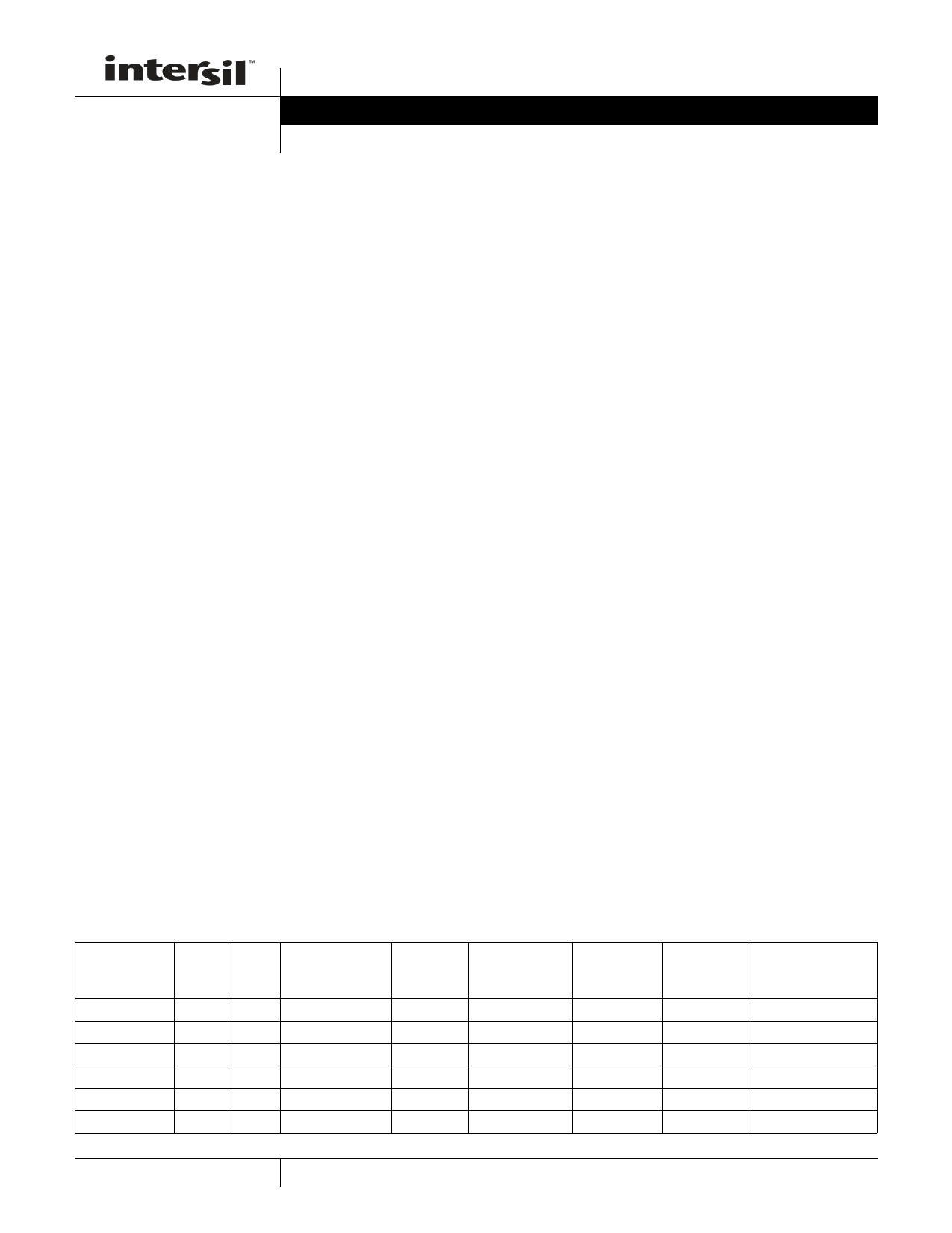
Table 1 summarizes the features of the devices represented
by this data sheet, while Application Note AN9863
summarizes the features of each device comprising the
ICL32XX 3V family.
Features
• Pb-Free Plus Anneal Available as an Option
(RoHS Compliant) (See Ordering Info)
• 15kV ESD Protected (Human Body Model)
• Drop in Replacements for MAX3221, MAX3222,
MAX3223, MAX3232, MAX3241, MAX3243, SP3243
• ICL3221 is Low Power, Pin Compatible Upgrade for 5V
MAX221
• ICL3222 is Low Power, Pin Compatible Upgrade for 5V
MAX242, and SP312A
• ICL3232 is Low Power Upgrade for HIN232/ICL232 and
Pin Compatible Competitor Devices
• RS-232 Compatible with VCC = 2.7V
• Meets EIA/TIA-232 and V.28/V.24 Specifications at 3V
• Latch-Up Free
• On-Chip Voltage Converters Require Only Four External
0.1F Capacitors
• Manual and Automatic Powerdown Features (Except
ICL3232)
• Guaranteed Mouse Driveability (ICL324X Only)
• Receiver Hysteresis For Improved Noise Immunity
• Guaranteed Minimum Data Rate . . . . . . . . . . . . . 250kbps
• Guaranteed Minimum Slew Rate . . . . . . . . . . . . . . . 6V/s
• Wide Power Supply Range . . . . . . . Single +3V to +5.5V
• Low Supply Current in Powerdown State. . . . . . . . . . .1A
Applications
• Any System Requiring RS-232 Communication Ports
- Battery Powered, Hand-Held, and Portable Equipment
- Laptop Computers, Notebooks, Palmtops
- Modems, Printers and other Peripherals
- Digital Cameras
- Cellular/Mobile Phones
NO. OF NO. OF
PART NUMBER Tx.
Rx.
ICL3221
11
ICL3222
22
ICL3223
22
ICL3232
22
ICL3241
35
ICL3243
35
TABLE 1. SUMMARY OF FEATURES
NO. OF
MONITOR Rx.
(ROUTB)
0
DATA
RATE
(kbps)
250
Rx. ENABLE
FUNCTION?
Yes
READY
OUTPUT?
No
0 250 Yes No
0 250 Yes No
0 250 No No
2 250 Yes No
1 250 No No
MANUAL
POWER-
DOWN?
Yes
Yes
Yes
No
Yes
Yes
AUTOMATIC
POWERDOWN
FUNCTION?
Yes
No
Yes
No
No
Yes
1
CAUTION: These devices are sensitive to electrostatic discharge; follow proper IC Handling Procedures.
1-888-INTERSIL or 1-888-468-3774 | Intersil (and design) is a registered trademark of Intersil Americas LLC.
Copyright Intersil Americas LLC. 1999-2006, 2015. All Rights Reserved
All other trademarks mentioned are the property of their respective owners.
1 page 
ICL3221, ICL3222, ICL3223, ICL3232, ICL3241, ICL3243
Typical Operating Circuits
ICL3221
C3 (OPTIONAL CONNECTION, NOTE)
+3.3V
+
0.1F
C1
0.1F
C2
0.1F
2
+
C1+
4 C1-
5
+
C2+
6 C2-
11
T1IN
15
VCC
T1
3
V+
+ C3
0.1F
V- 7
13
C4
+0.1F
T1OUT
R1OUT
9
1 EN
8
R1 5k
16
FORCEOFF
12 10
FORCEON
INVALID
GND
14
R1IN
VCC
TO POWER
CONTROL
LOGIC
NOTE: The negative terminal of C3 can be
connected to either VCC or GND
+3.3V
+
0.1F
C1
0.1F
C2
0.1F
2
+
4
5
+6
C1+
C1-
C2+
C2-
12
T1IN
T2IN
11
ICL3222
C3 (OPTIONAL CONNECTION, NOTE)
17
VCC
T1
T2
V+ 3 + C0.31F
V- 7 C4
+ 0.1F
15
T1OUT
8
T2OUT
R1OUT 13
R2OUT
10
1 EN
14
R1IN
R1 5k
9
R2 5k
R2IN
GND
16
18
SHDN
VCC
NOTE: The negative terminal of C3 can be
connected to either VCC or GND
+3.3V
+ 0.1F
C1
0.1F
C2
0.1F
2
+
C1+
4 C1-
5
+6
C2+
C2-
13
T1IN
12
T2IN
ICL3223
19
VCC
T1
T2
3
V+
+ C3
0.1F
V- 7
17
C4
+0.1F
T1OUT
8
T2OUT
R1OUT
R2OUT
15 16
R1 5k
10 9
1 EN
R2 5k
20
FORCEOFF
14
FORCEON
11
INVALID
GND
18
R1IN
R2IN
VCC
TO POWER
CONTROL LOGIC
5
+3.3V
+
0.1F
C1
0.1F
C2
0.1F
1
+
C1+
3 C1-
4
+
C2+
5
C2-
11
T1IN
10
T2IN
ICL3232
C3 (OPTIONAL CONNECTION, NOTE)
16
VCC
T1
T2
2
V+
+
C3
0.1F
V- 6
14
C4
+0.1F
T1OUT
7
T2OUT
R1OUT 12
9
R2OUT
R1
R2
GND
15
13
5k
8
5k
R1IN
R2IN
NOTE: The negative terminal of C3 can be
connected to either VCC or GND
FN4805.22
September 1, 2015
5 Page 
ICL3221, ICL3222, ICL3223, ICL3232, ICL3241, ICL3243
The INVALID output always indicates whether or not a valid
RS-232 signal is present at any of the receiver inputs (See
Table 2), giving the user an easy way to determine when the
interface block should power down. In the case of a
disconnected interface cable where all the receiver inputs
are floating (but pulled to GND by the internal receiver pull
down resistors), the INVALID logic detects the invalid levels
and drives the output low. The power management logic
then uses this indicator to power down the interface block.
Reconnecting the cable restores valid levels at the receiver
inputs, INVALID switches high, and the power management
logic wakes up the interface block. INVALID can also be
used to indicate the DTR or RING INDICATOR signal, as
long as the other receiver inputs are floating, or driven to
GND (as in the case of a powered down driver). Connecting
FORCEOFF and FORCEON together disables the
automatic powerdown feature, enabling them to function as
a manual SHUTDOWN input (See Figure 4).
VCC
VCC
VCC
CURRENT
FLOW
POWERED
DOWN
UART
GND
VOUT = VCC
Rx
Tx
SHDN = GND
OLD
RS-232 CHIP
FIGURE 2. POWER DRAIN THROUGH POWERED DOWN
PERIPHERAL
VCC
TRANSITION
DETECTOR
TO
WAKE-UP
LOGIC
VCC
R2OUTB
RX
POWERED
DOWN
UART
TX
VOUT = HI-Z
R2OUT
T1IN
ICL324X
FORCEOFF = GND
OR SHDN = GND, EN = VCC
R2IN
T1OUT
FIGURE 3. DISABLED RECEIVERS PREVENT POWER DRAIN
PWR
MGT
LOGIC
FORCEOFF
FORCEON
INVALID
ICL3221/23/43
CPU
I/O
UART
FIGURE 4. CONNECTIONS FOR MANUAL POWERDOWN
WHEN NO VALID RECEIVER SIGNALS ARE
PRESENT
With any of the above control schemes, the time required to
exit powerdown, and resume transmission is only 100s. A
mouse, or other application, may need more time to wake up
from shutdown. If automatic powerdown is being utilized, the
RS-232 device will reenter powerdown if valid receiver levels
aren’t reestablished within 30s of the ICL32XX powering
up. Figure 5 illustrates a circuit that keeps the ICL32XX from
initiating automatic powerdown for 100ms after powering up.
This gives the slow-to-wake peripheral circuit time to
reestablish valid RS-232 output levels.
POWER
MANAGEMENT
UNIT
MASTER POWERDOWN LINE
0.1F
1M
FORCEOFF FORCEON
ICL3221/23/43
FIGURE 5. CIRCUIT TO PREVENT AUTO POWERDOWN FOR
100ms AFTER FORCED POWERUP
Automatic Powerdown (ICL3221/23/43 Only)
Even greater power savings is available by using the
devices which feature an automatic powerdown function.
When no valid RS-232 voltages (See Figure 6) are sensed
on any receiver input for 30s, the charge pump and
transmitters powerdown, thereby reducing supply current to
1A. Invalid receiver levels occur whenever the driving
peripheral’s outputs are shut off (powered down) or when the
RS-232 interface cable is disconnected. The ICL32XX
powers back up whenever it detects a valid RS-232 voltage
level on any receiver input. This automatic powerdown
feature provides additional system power savings without
changes to the existing operating system.
11 FN4805.22
September 1, 2015
11 Page | ||
| Páginas | Total 28 Páginas | |
| PDF Descargar | [ Datasheet ICL3241.PDF ] | |
Hoja de datos destacado
| Número de pieza | Descripción | Fabricantes |
| ICL3241 | 1 Microamp Supply-Current/ +3V to +5.5V/ 250kbps/ RS-232 Transmitters/Receivers | Intersil |
| ICL3241E | (ICL32xxE) RS-232 Transmitters/Receivers | Intersil Corporation |
| ICL3243 | 1 Microamp Supply-Current/ +3V to +5.5V/ 250kbps/ RS-232 Transmitters/Receivers | Intersil |
| ICL3243E | (ICL32xxE) RS-232 Transmitters/Receivers | Intersil Corporation |
| Número de pieza | Descripción | Fabricantes |
| SLA6805M | High Voltage 3 phase Motor Driver IC. |
Sanken |
| SDC1742 | 12- and 14-Bit Hybrid Synchro / Resolver-to-Digital Converters. |
Analog Devices |
|
DataSheet.es es una pagina web que funciona como un repositorio de manuales o hoja de datos de muchos de los productos más populares, |
| DataSheet.es | 2020 | Privacy Policy | Contacto | Buscar |