|
|
|
PDF ICL232 Data sheet ( Hoja de datos )
| Número de pieza | ICL232 | |
| Descripción | Dual RS-232 Transmitter/Receiver | |
| Fabricantes | Intersil | |
| Logotipo | ||
Hay una vista previa y un enlace de descarga de ICL232 (archivo pdf) en la parte inferior de esta página. Total 8 Páginas | ||
|
No Preview Available !
DATASHEET
+5V Powered, Dual RS-232 Transmitter/Receiver
ICL232
The ICL232 is a dual RS-232 transmitter/receiver interface
circuit that meets all ElA RS-232C and V.28 specifications. It
requires a single +5V power supply, and features two onboard
charge pump voltage converters which generate +10V and
-10V supplies from the 5V supply.
The drivers feature true TTL/CMOS input compatibility,
slew-rate-limited output, and 300Ω power-off source
impedance. The receivers can handle up to +30V, and have a
3kΩ to 7kΩ input impedance. The receivers also have
hysteresis to improve noise rejection.
Applications
• Any system requiring RS-232 communications port
- Computer - portable and mainframe
- Peripheral - printers and terminals
- Portable instrumentation
- Modems
• Dataloggers
Features
• Meets all RS-232C and V.28 specifications
• Requires only single +5V power supply
• Onboard voltage doubler/inverter
• Low power consumption
• 2 drivers
- 9V output swing for +5V lnput
- 300Ω power-off source impedance
- Output current limiting
- TTL/CMOS compatible
- 30V/µs maximum slew rate
• 2 Receivers
- 30V input voltage range
- 3kΩ to 7kΩ input impedance
- 0.5V hysteresis to improve noise rejection
• All critical parameters are guaranteed over the entire
commercial, industrial and military temperature ranges
• Pb-free (RoHS compliant)
+
1.0µF
+5V
16
1µF
1µF
T1IN
T2IN
R1OUT
R2OUT
1
+
3
C1+
C1-
VCC
+5V TO 10V
VOLTAGE INVERTER
V+
2
4
+
C2+
+10V TO -10V
5 C2- VOLTAGE INVERTER
V- 6
+5V T1
11 400kΩ
14
+5V
10 400kΩ
12
T2
7
13
R1 5kΩ
+ 1µF
+ 1µF
T1OUT
T2OUT
R1IN
9 8 R2IN
R2 5kΩ
15
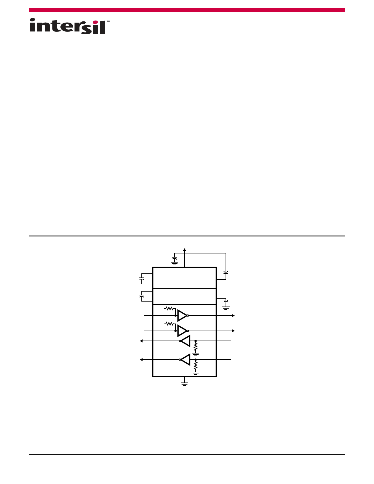
FIGURE 1. FUNCTIONAL DIAGRAM
October 15, 2014
FN3020.8
1
CAUTION: These devices are sensitive to electrostatic discharge; follow proper IC Handling Procedures.
1-888-INTERSIL or 1-888-468-3774 | Copyright Intersil Americas LLC 2001, 2005, 2014. All Rights Reserved
Intersil (and design) is a trademark owned by Intersil Corporation or one of its subsidiaries.
All other trademarks mentioned are the property of their respective owners.
1 page 
ICL232
Detailed Description
The ICL232 is a dual RS-232 transmitter/receiver powered by a
single +5V power supply which meets all ElA RS232C
specifications and features low power consumption. Figure 1
illustrates the major elements of the ICL232. The circuit is divided
into three sections: a voltage doubler/inverter, dual transmitters,
and dual receivers.
Voltage Converter
An equivalent circuit of the dual charge pump is illustrated in
Figure 6.
The voltage quadrupler contains two charge pumps which use two
phases of an internally generated clock to generate +10V and
-10V. The nominal clock frequency is 16kHz. During phase one of
the clock, capacitor C1 is charged to VCC. During phase two, the
voltage on C1 is added to VCC, producing a signal across C2 equal
to twice VCC. At the same time, C3 is also charged to 2VCC, and
then during phase one, it is inverted with respect to ground to
produce a signal across C4 equal to -2VCC. The voltage converter
accepts input voltages up to 5.5V. The output impedance of the
doubler (V+) is approximately 200Ω, and the output impedance of
the inverter (V-) is approximately 450Ω . Typical graphs are
presented which show the voltage converters output vs input
voltage and output voltages vs load characteristics. The test circuit
(Figure 2) uses 1µF capacitors for C1 to C4, however, the value is
not critical. Increasing the values of C1 and C2 will lower the
output impedance of the voltage doubler and inverter, and
increasing the values of the reservoir capacitors, C3 and C4,
lowers the ripple on the V+ and V- supplies.
T1IN, T2IN
T1OUT, T2OUT
90%
10%
tf
tr
VOH
VOL
Instantaneous
Slew Rate (SR)
=
(0.8) (VOH - VOL)
tr
or
(0.8) (VOL - VOH)
tf
FIGURE 7. SLEW RATE DEFINITION
Transmitters
The transmitters are TTL/CMOS compatible inverters which
translate the inputs to RS-232 outputs. The input logic threshold is
about 26% of VCC , or 1.3V for VCC = 5V. A logic 1 at the input
results in a voltage of between -5V and V- at the output, and a logic
0 results in a voltage between +5V and (V+ - 0.6V). Each
transmitter input has an internal 400kΩ pullup resistor so any
unused input can be left unconnected and its output remains in its
low state. The output voltage swing meets the RS-232C
specification of 5V minimum with the worst case conditions of:
both transmitters driving 3kΩ minimum load impedance,
VCC = 4.5V, and maximum allowable operating temperature. The
transmitters have an internally limited output slew rate which is
less than 30V/µs. The outputs are short circuit protected and can
be shorted to ground indefinitely. The powered down output
impedance is a minimum of 300Ω with 2V applied to the outputs
and VCC = 0V.
V+
VCC
TXIN
400kΩ
300Ω
TOUT
GND < TXIN < VCC
V- < VTOUT < V+
V-
FIGURE 8. TRANSMITTER
Receivers
The receiver inputs accept up to 30V while presenting the
required 3kΩ to 7kΩ input impedance even it the power is off
(VCC = 0V). The receivers have a typical input threshold of 1.3V
which is within the 3V limits, known as the transition region, of
the RS-232 specification. The receiver output is 0V to VCC. The
output will be low whenever the input is greater than 2.4V and
high whenever the input is floating or driven between +0.8V and
-30V. The receivers feature 0.5V hysteresis to improve noise
rejection.
VCC
RXIN
-30V < RXIN < +30V
GND
5kΩ
ROUT
GND < VROUT < VCC
FIGURE 9. RECEIVER
T1IN, T2IN
OR
R1IN, R2IN
T1OUT, T2OUT
OR
R1OUT, R2OUT
tPHL
tPLH
VOH
VOL
Average
Propagation
Delay
=
tPHL
+
2
tPLH
FIGURE 10. PROPAGATION DELAY DEFINITION
Applications
The ICL232 may be used for all RS-232 data terminal and
communication links. It is particularly useful in applications
where 12V power supplies are not available for conventional
RS-232 interface circuits. The applications presented represent
typical interface configurations.
A simple duplex RS-232 port with CTS/RTS handshaking is
illustrated in Figure 11. Fixed output signals such as DTR (data
terminal ready) and DSRS (data signaling rate select) is
generated by driving them through a 5kΩ resistor connected to
V+.
Submit Document Feedback
5
FN3020.8
October 15, 2014
5 Page | ||
| Páginas | Total 8 Páginas | |
| PDF Descargar | [ Datasheet ICL232.PDF ] | |
Hoja de datos destacado
| Número de pieza | Descripción | Fabricantes |
| ICL232 | Dual RS-232 Transmitter/Receiver | Intersil |
| ICL232 | +5V Powered Dual RS-232 Transmitter/Receiver | Harris Corporation |
| Número de pieza | Descripción | Fabricantes |
| SLA6805M | High Voltage 3 phase Motor Driver IC. |
Sanken |
| SDC1742 | 12- and 14-Bit Hybrid Synchro / Resolver-to-Digital Converters. |
Analog Devices |
|
DataSheet.es es una pagina web que funciona como un repositorio de manuales o hoja de datos de muchos de los productos más populares, |
| DataSheet.es | 2020 | Privacy Policy | Contacto | Buscar |