|
|
|
PDF ZSM561G Data sheet ( Hoja de datos )
| Número de pieza | ZSM561G | |
| Descripción | SUPPLY VOLTAGE MONITOR | |
| Fabricantes | Zetex Semiconductors | |
| Logotipo | ||
Hay una vista previa y un enlace de descarga de ZSM561G (archivo pdf) en la parte inferior de esta página. Total 6 Páginas | ||
|
No Preview Available !
SUPPLY VOLTAGE
MONITOR
ISSUE 3 – JANUARY 1998
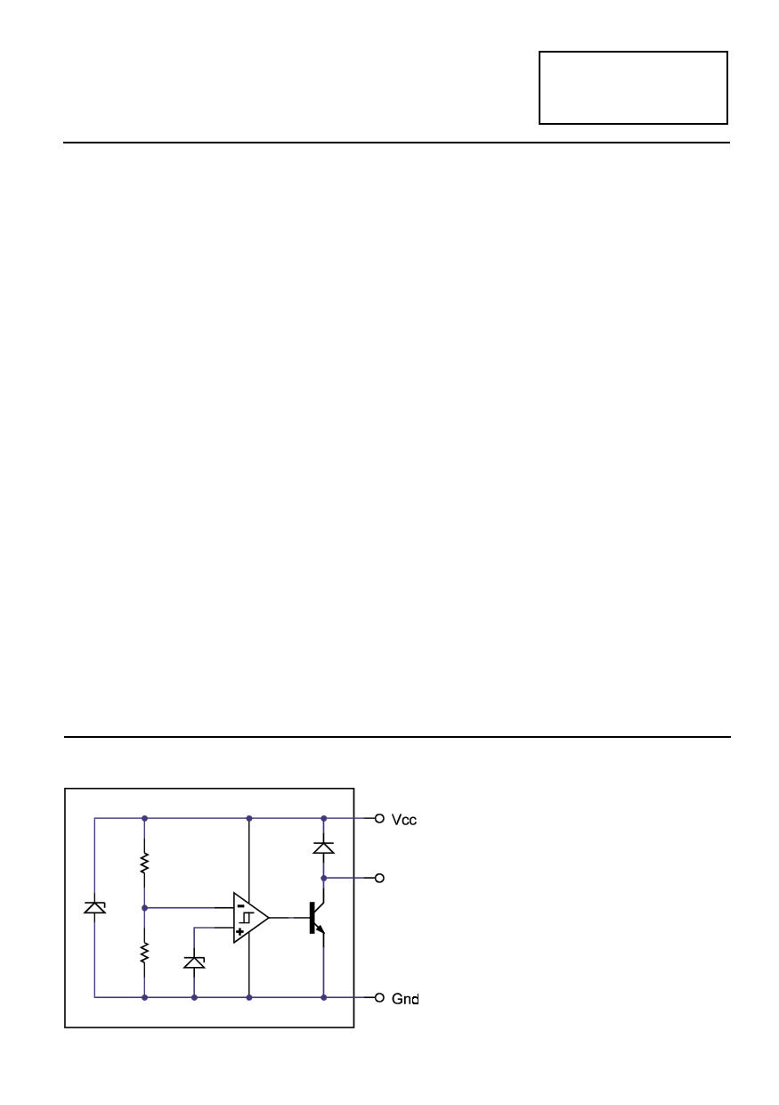
DEVICE DESCRIPTION
The ZSM561 is a three terminal under
voltage monitor circuit for use in
microprocessor systems. The threshold
voltage of the device has been set to 4.6 volts
making it ideal for 5 volt circuits.
Included in the device is a precise voltage
reference and a comparator with built in
hysteresis to prevent erratic operation. The
ZSM561 features an open collector output
capable of sinking at least l0mA which only
requires a single external resistor to
interface to following circuits.
Operation of the device is guaranteed from
one volt upwards, from this level to the
device threshold voltage the output is held
low providing a power on reset function.
Should the supply voltage, once established,
at any time drop below the threshold level
then the output again will pull low. Also
included is a 6 volt zener diode connected
between Vcc and Gnd. With just the addition
of a low cost external NPN transistor and
resistor, this zener allows the ZSM561 to
provide both regulator and supply monitor
functions
The device is available in a TO92 package for
through hole applications as well as SO8 and
SOT223 for surface mount requirements.
SCHEMATIC DIAGRAM
ZSM561
FEATURES
• SO8, SOT223 and TO92 packages
• Power on reset generator
• Automatic reset generation
• Low standby current
• Guaranteed operation from 1 volt
• Wide supply voltage range
• Internal clamp diode to discharge
delay capacitor
• 4.6 volt threshold for 5 volt logic
• 20mV hysteresis prevents erratic operation
APPLICATIONS
• Microprocessor systems
• Computers
• Computer peripherals
• Instrumentation
• Automotive
• Battery powered equipment
4-364
1 page 
ZSM561
APPLICATION CIRCUITS
TDY
=
RCd
ln
1
−
1
VTH(mpu)
Vin
TDY = Time (Seconds)
VTH = Microprocessor ResetThreshold
Vin = Power Supply Voltage
RB =
(VINMIN − 6)
(IQ
+
IL
hFE
)
VINMIN = The minimum input voltage provided
by the unregulated supply.
IQ = The ZSM561 quiescent current (ie 200 µA)
IL = Load current taken by the microprocessor
system.
hFE = The minimum hFE that can be expected
from the pass transistor under worst case
conditions. (ie Lowest temperature and
minimum input voltage). For the ZTX690B a
value of 250 could be used.
4-368
5 Page | ||
| Páginas | Total 6 Páginas | |
| PDF Descargar | [ Datasheet ZSM561G.PDF ] | |
Hoja de datos destacado
| Número de pieza | Descripción | Fabricantes |
| ZSM561 | SUPPLY VOLTAGE MONITOR | Zetex Semiconductors |
| ZSM561C | SUPPLY VOLTAGE MONITOR | Zetex Semiconductors |
| ZSM561G | SUPPLY VOLTAGE MONITOR | Zetex Semiconductors |
| ZSM561N8 | SUPPLY VOLTAGE MONITOR | Zetex Semiconductors |
| Número de pieza | Descripción | Fabricantes |
| SLA6805M | High Voltage 3 phase Motor Driver IC. |
Sanken |
| SDC1742 | 12- and 14-Bit Hybrid Synchro / Resolver-to-Digital Converters. |
Analog Devices |
|
DataSheet.es es una pagina web que funciona como un repositorio de manuales o hoja de datos de muchos de los productos más populares, |
| DataSheet.es | 2020 | Privacy Policy | Contacto | Buscar |