|
|
|
PDF ZR36067 Data sheet ( Hoja de datos )
| Número de pieza | ZR36067 | |
| Descripción | AV PCI CONTROLLER | |
| Fabricantes | ETC | |
| Logotipo | ||
Hay una vista previa y un enlace de descarga de ZR36067 (archivo pdf) en la parte inferior de esta página. Total 30 Páginas | ||
|
No Preview Available !
DATA SHEET
ZR36067
AV PCI CONTROLLER
FEATURES
T Supersedes the Zoran ZR36057.
T Glueless interface to PCI bus (PCI spec. 2.1 compliant).
T Minimum interface to JPEG decoders (ZR36060,
ZR36050+ZR36016), MPEG1 and DVD decoders
(ZR36110, ZR36700), video decoders and video encoders.
T Bidirectional DMA transfer of compressed data up to 11M
bytes/sec.
T DMA transfer of video and mask information.
T Support for fast still image compression and decompression.
T Smooth image down-scaler (up to 5-tap horizontal filter).
T On-chip pixel accurate masking.
T YUV-to-RGB converter with quantization noise reduction by
error diffusion.
T Video output: 15- and 16-bit RGB pixel formats, as well as
24-bit (packed and unpacked), and YUV 4:2:2.
T Hardware support for non-contiguous JPEG code buffers.
T Graceful recovery from extreme bus latencies both on video
and code transfers.
T Choice of emulated interlaced video display, or single field
display, to eliminate motion artifacts.
T Hardware support for simple, cost effective frame grabbing.
T I2C bus master port.
T Plug & Play support.
T 208-pin PQFP package.
T Support for Subsystem ID and Subsystem Vendor ID.
APPLICATIONS
T High quality video and audio capture/playback and editing
boards for PCI systems.
T Multimedia/Graphics subsystems using a secondary PCI
bus.
T PCI motherboards with multimedia capability.
T JPEG/MPEG1 solutions for PowerPC and Macintosh PCI
systems.
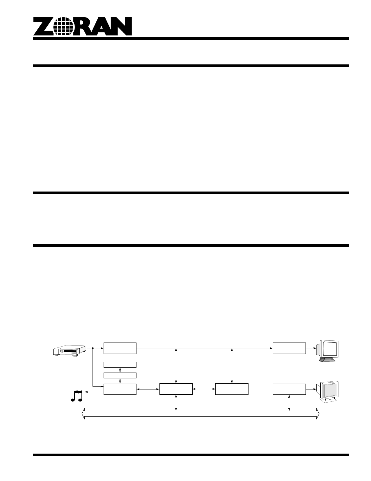
Video Decoder
Audio Control
Audio FIFO
Audio Codec
ZR36067
ZR36060
PCI Bus
Video Encoder
Graphics
Sub-System
Figure 1. Block Diagram of a Typical Motion JPEG System for PCI
T T T TZORAN Corporation 3112 Scott Blvd Santa Clara, CA 95054 (408) 919-4111 FAX (408) 919-4122
February 1998
1 page 
AV PCI CONTROLLER
1.2.5 Notations and Conventions
External signals:
Active-low mark [1]:
Capital letters (e.g., IDSEL)
Overbar (e.g., DEVSEL)
Internal function units: capital (non-bold) letters (e.g., VFE)
Buses:
XXmsb_index..lsb_index (e.g., AD31..0)
Register fields:
XXmsb_index:lsb_index (e.g., Mode27:16)
Register types:
R - read only
RC - read-clear. Writing ‘1’ clears the register bit.
RS - read-set. Writing ‘1’ sets the register bit to ‘1’.
RW - read-write (contents of write can be read back)
W - write only (contents of read are meaningless)
Numbers:
Unmarked numbers are decimal (e.g., 365, 23.19). Hexadecimal numbers are marked with a ‘0x’ prefix (e.g., 0xB000,
0x3). Binary numbers are marked with a ‘b’ suffix (e.g., 010b, 0000110100011b).
1. In this document, an overbar is used to denote active low signals. In other documents referenced herein, such as the PCI specifications, the # suffix notation is often
used instead. The two forms of notation are interchangeable. Thus, for example, DEVSEL is equivalent to DEVSEL#.
5
5 Page 
AV PCI CONTROLLER
the extended 24-bit video bus and the synchronization signals in
order to drive the pixels to the ZR36016 or get them from it, as
appropriate.
The following four subsections detail the four basic functions of
the Video Interface:
• Sampling the incoming video.
• Generating the synchronization signals.
• Pixel transfer in Still Image Compression.
• Pixel transfer in Still Image Decompression.
5.2.1 Sampling The Incoming Video
The ZR36067’s Video Front End (VFE) interfaces to a standard
YUV 4:2:2 video bus. It samples the Y7..0, UV7..0, HSYNC and
VSYNC with every other positive edge of VCLKx2. The valid
positive edge (out of every two consecutive ones), which is the
one used for sampling, is qualified by VCLK. The qualifying
polarity of VCLK is configured by the host. This scheme makes
the ZR36067 compatible with a wide range of digital video
sources and immune to board-level parasitic delays. VCLKx2
(positive edges) is used internally in the video processing
pipeline.
The VFE generates a field indication signal targeted to some
internal video processing units. There are two alternative ways
of generating the field indication. With devices that output a field
indication, the VFE uses the FI input as an indicator of the
current field identity. The interpretation of the logical level of FI
(top or bottom field) is configured by the host. With devices that
do not provide such an indication, the VFE infers the field identity
from the relationship of HSYNC to VSYNC.
The VFE can capture square pixel and CCIR-601 formats, or
user defined formats, within the limitation of its parameters. The
maximum theoretical total input resolution is 1023 pixels/line x
1023 lines per frame. Cropping of the input image is possible by
proper configuration of the VFE parameters.
Table 1 lists the Video Front End parameters. The host software
needs to configure these parameters according to the timing
parameters of the video source (e.g., SAA7110, SAA7111,
ZR36060, etc.) and the required cropping. Note that these
parameters relate to the input video, and not to the destination
video window.
Table 1: Video Front-End Parameters
Parameter
VStart
HStart
VEnd
Description
Number of lines (HSYNCs) from the active edge (pos-
itive or negative, according to VSPol) of VSYNC to the
first line to be sampled.
Number of pixel clocks in a line from the active edge of
HSYNC until the first pixel to be sampled.
Number of lines (HSYNCs) from the active edge (pos-
itive or negative, according to VSPol) of VSYNC to the
last line to be sampled.
Table 1: Video Front-End Parameters
Parameter
HEnd
ExtFI
HSPol
VSPol
TopField
VCLKPol
Description
Number of pixel clocks in a line from the active edge of
HSYNC until the last pixel to be sampled.
This one bit parameter indicates whether the video
source provides a field indication signal.
The HSYNC polarity. HStart and HEnd are counted
from the active edge of HSYNC. ‘1’ means that HStart,
HEnd will be counted from the negative edge of
HSYNC. Also determines signal polarity when
SyncMstr=’1’.
The VSYNC polarity. VStart and VEnd are counted
from the active edge of VSYNC. ‘1’ means that VStart,
VEnd will be counted from the negative edge of
VSYNC. Also determines signal polarity when
SyncMstr=’1’.
Top Field Interpretation. If field indication is derived
from the FI input signal (see ExtFI), TopField indicates
the interpretation of the FI signal:
TopField=‘1’ - FI high indicates the top field.
TopField=‘0’ - FI low indicates the top field.
If field indication is derived internally from HSYNC and
VSYNC, TopField indicates the interpretation of the
level of HSYNC as sampled by the active edge of
VSYNC:
TopField=‘1’ - HSYNC high indicates the top field.
TopField=‘0’ - HSYNC low indicates the top field.
Polarity of VCLK as a data qualifier. If VCLKPol=1 the
video input is sampled with those positive edges of
VCLKx2 that correspond to VCLK=1. If VCLKPol=0,
the video input is sampled by those positive edges of
VCLKx2 that correspond to VCLK=0.
5.2.2 Synchronization Signal Generation
The ZR36067 supports internal generation of the video synchro-
nization signals. In this mode (when SyncMstr=1) the ZR36067
generates and drives VSYNC and HSYNC signals. Using
software programmable parameters, the ZR36067 can generate
various video synchronization signal formats.
Table 3 lists the sync signal parameters. The host software con-
figures those parameters according the mode of operation and
the video peripheral devices used. Note that he polarity of the
sync signals is determined by the VSPol and HSPol parameters
(Table 2).
Table 2: Synchronization Signal Parameters
Parameter
FrmTot
LineTot
VsyncSize
Hsync Start
Meaning
Total number of lines per frame
(e.g., in NTSC: 525)
Total number of pixel clocks per line
(e.g., in CCIR NTSC: 858)
The length of the VSYNC signal, measured in
lines.
The point in the scan line at which the HSYNC
signal should be asserted.
11
11 Page | ||
| Páginas | Total 30 Páginas | |
| PDF Descargar | [ Datasheet ZR36067.PDF ] | |
Hoja de datos destacado
| Número de pieza | Descripción | Fabricantes |
| ZR36060 | Integrated JPEG CODEC | ETC |
| ZR36060PQC | Integrated JPEG CODEC | ETC |
| ZR36067 | AV PCI CONTROLLER | ETC |
| Número de pieza | Descripción | Fabricantes |
| SLA6805M | High Voltage 3 phase Motor Driver IC. |
Sanken |
| SDC1742 | 12- and 14-Bit Hybrid Synchro / Resolver-to-Digital Converters. |
Analog Devices |
|
DataSheet.es es una pagina web que funciona como un repositorio de manuales o hoja de datos de muchos de los productos más populares, |
| DataSheet.es | 2020 | Privacy Policy | Contacto | Buscar |