|
|
|
PDF PCM1732 Data sheet ( Hoja de datos )
| Número de pieza | PCM1732 | |
| Descripción | 24-Bit/ 96kHz/ Stereo Audio DIGITAL-TO-ANALOG CONVERTER With HDCD Decoder | |
| Fabricantes | Burr-Brown Corporation | |
| Logotipo | ||
Hay una vista previa y un enlace de descarga de PCM1732 (archivo pdf) en la parte inferior de esta página. Total 18 Páginas | ||
|
No Preview Available !
®
49%
PCM1732
FPO
®
®
For most current data sheet and other product
information, visit www.burr-brown.com
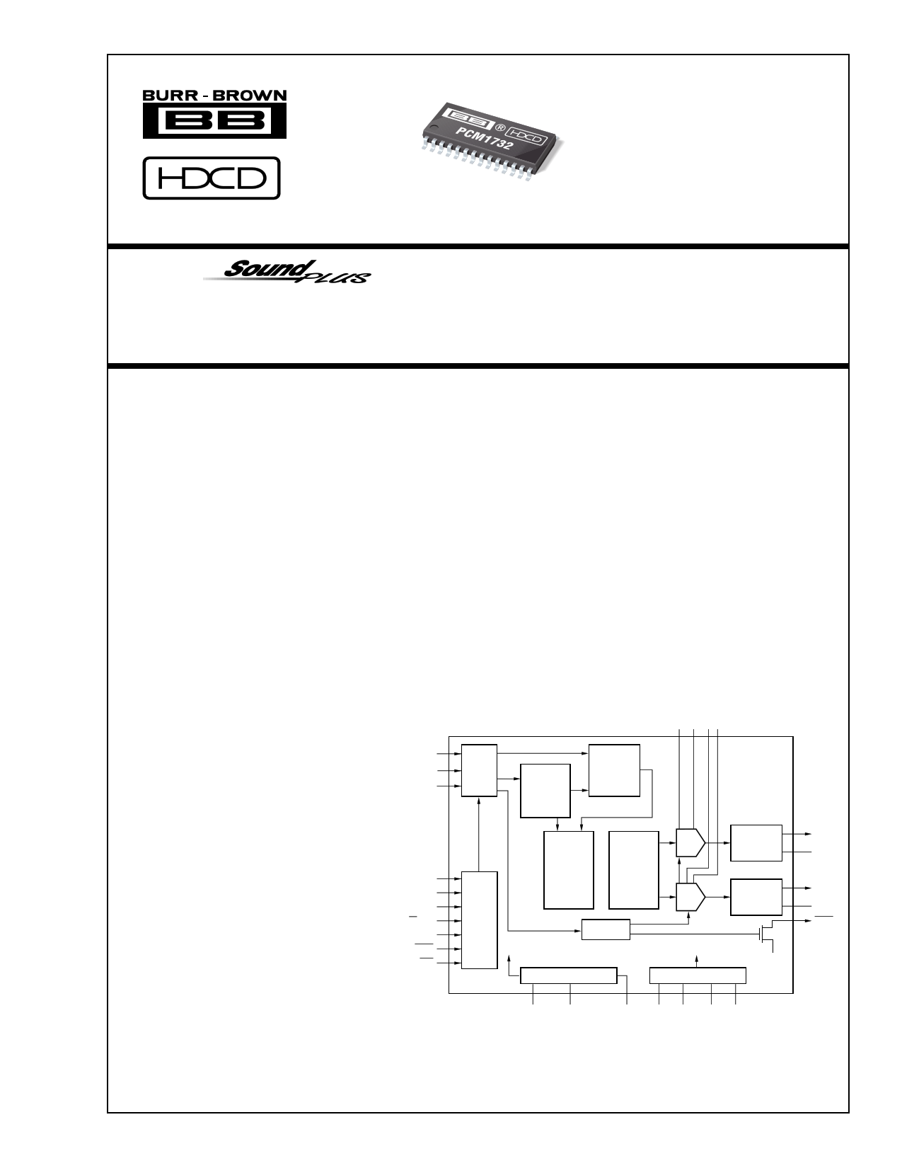
TM 24-Bit, 96kHz, Stereo Audio
DIGITAL-TO-ANALOG CONVERTER
With HDCD® Decoder
FEATURES
DESCRIPTION
q ENHANCED MULTI-LEVEL ∆Σ DAC
The PCM1732 is designed for mid- to high-grade
q INPUT AUDIO DATA WORD: 16-, 20-, 24-Bit
q SAMPLING FREQUENCY (fs): 16kHz - 96kHz
q SYSTEM CLOCK: 256, 384, 512, 768fS
q HIGH PERFORMANCE:
THD+N: –96dB
Dynamic Range: 104dB
SNR: 104dB
digital audio applications which achieve 96kHz sam-
pling rates with 24-bit audio data, such as High Defi-
nition Compatible Digital (HDCD) CD players, DVD
players, mini-disc players and AV receivers.
PCM1732 uses a newly-developed “enhanced, multi-
level delta-sigma modulator” architecture that im-
proves audio dynamic performance and reduces jitter
q AUDIO OUTPUT LEVEL: 0.57 x VCC (Vp-p)
q 8x OVERSAMPLING DIGITAL FILTER WITH
HDCD DECODER:
Stopband Attenuation: –120dB
Passband Ripple: ±0.00001dB
HDCD Filter Optimized for 44.1kHz to 48kHz
sensitivity.
The internal digital filter operates at 8x oversampling
at a 96kHz sampling rate, with –120dB stopband
attenuation.
and 88.2kHz to 96kHz
q MULTI-FUNCTIONS:
Digital De-emphasis
Soft Mute
Digital Attenuation
Zero Detect
Digital Gain Scaling
Reversible Output Phase
BCKIN
LRCIN
DIN
Serial
Input
I/F
HDCD
Hidden
Code
Recovery
HDCD
Amplitude
Decoding
PCM1732
q +5V SINGLE-SUPPLY OPERATION
q SMALL SO-28 PACKAGE
NOTE: An HDCD license from Pacific Microsonics, Inc. is
required to purchase the PCM1732.
ML/I2S
MC/DEM
MD/FSS
CS/IWO
MODE
Mode
Control
I/F
HDCD
8x
Oversampling
Digital Filter
Enhanced
Multi-Level
∆Σ
Modulator
BPZ Control
DAC
DAC
Low-Pass
Filter
Low-Pass
Filter
VOUTL
EXTL
VOUTR
EXTR
ZERO
HDCD® is a registered trademark of Pacific Microsonics, Inc.
MUTE
RST
SCK
Crystal/OSC
Power-On Reset
Power Supply
Open
Drain
HDCD® technology is provided under license from Pacific Microsonics
Inc. The PCM1732’s design is covered by the following patents:
In the USA: 45,479,168, 5,638,074, 5,640,161, 5,808,574, 5,838,274
5,854,600, 5,864,311, 5,872,531.
In Australia: 669,114.
Other patents pending.
XTI XTO
CLKO VCC1 AGND1 VDD DGND
International Airport Industrial Park • Mailing Address: PO Box 11400, Tucson, AZ 85734 • Street Address: 6730 S. Tucson Blvd., Tucson, AZ 85706 • Tel: (520) 746-1111
Twx: 910-952-1111 • Internet: http://www.burr-brown.com/ • Cable: BBRCORP • Telex: 066-6491 • FAX: (520) 889-1510 • Immediate Product Info: (800) 548-6132
© 1999 Burr-Brown Corporation
PDS-1522B
Printed in U.S.A. August, 1999
1 page 
TYPICAL PERFORMANCE CURVES
All specifications at +25°C, +VCC = +VDD = +5V, fS = 44.1kHz, and 24-bit input data, SYSCLK = 384fS, unless otherwise noted.
–60dB AMPLITUDE vs FREQUENCY
24-Bit Data
–60
–70
–80
–90
–100
–110
–120
–130
–140
0 2 4 6 8 10 12 14 16 18 20
Frequency (kHz)
–60dB AMPLITUDE vs FREQUENCY
16-Bit Data
–60
–70
–80
–90
–100
–110
–120
–130
–140
0 2 4 6 8 10 12 14 16 18 20
Frequency (kHz)
–60
–70
–80
–90
–100
–110
–120
–130
–140
0
2
–60dB AMPLITUDE vs FREQUENCY
HDCD Without Peak Extend
4 6 8 10 12 14 16 18 20
Frequency (kHz)
–60dB AMPLITUDE vs FREQUENCY
HDCD With Peak Extend
–60
–70
–80
–90
–100
–110
–120
–130
–140
0 2 4 6 8 10 12 14 16 18 20
Frequency (kHz)
DYNAMIC RANGE vs SUPPLY VOLTAGE
108
107
fS = 44.1kHz, 24-Bit
106
105
104
HDCD with Peak Extend
103
102
101
100
99 fS = 44.1kHz, 16-Bit
98
4.25
4.50
4.75 5.00
5.25 5.50
Power Supply Voltage (V)
5.75
–86
–88
–90
–92
–94
–96
98
100
–102
4.25
THD+N vs SUPPLY VOLTAGE
HDCD With Peak Extend
fS = 44.1kHz, 16-Bit
fS = 44.1kHz, 24-Bit
4.50
4.75 5.00
5.25 5.50
Power Supply Voltage (V)
5.75
®
5 PCM1732
5 Page 
tMLL
tMHH
ML
tMCH
tMCL
MC
tMCY
MD
tMLH
LSB
1.4V
tMLS
1.4V
1.4V
tMDS
tMDH
tCSML
tMLCS
CS 1.4V
MC Pulse Cycle Time
MC Pulse Width LOW
MC Pulse Width HIGH
MD Hold Time
MD Set-up Time
ML Low Level Time
ML High Level Time
ML Hold Time
ML Set-up Time
CS LOW to ML LOW Time(2)
ML HIGH to CS HIGH Time(2)
: tMCY
: tMCL
: tMCH
: tMDH
: tMDS
: tMLL
: tMHH
: tMLH
: tMLS
: tCSML
: tMLCS
: 100ns (min)
: 40ns (min)
: 40ns (min)
: 40ns (min)
: 40ns (min)
: 40ns (min) + 1SYSCLK(1) (min)
: 40ns (min) + 1SYSCLK(1) (min)
: 40ns (min)
: 40ns (min)
: 10ns (min)
: 10ns (min)
NOTES: (1) System Clock Cycle. (2) CS should be changed during ML = HIGH.
FIGURE 9. Program Register Input Timing.
REGISTER
NAME
Register 0
Register 1
Register 2
Register 3
BIT
NAME
AL (7:0)
LDL
A (1:0)
res
AR (7:0)
LDR
A (1:0)
res
MUT
DEM
OPE
IW (1:0)
FSS
SCA
C3 (1:0)
A (1:0)
res
I2S
LRP
ATC
REV
CKO
SF (1:0)
IZD
A (1:0)
res
DESCRIPTION
DAC Attenuation Data for Lch
Attenuation Data Load Control for Lch
Register Address
Reserved, set to LOW
DAC Attenuation Data for Rch
Attenuation Data Load Control for Rch
Register Address
Reserved, set to LOW
Left and Right DACs Soft Mute Control
De-Emphasis Control
Left and Right DACs Operation Control
Input Audio Data Bit and Format Select
Sampling Rate Range Select
HDCD Grain Scaling Select
HDCD Hidden Code Location
Register Address
Reserved, set to LOW
Audio Data Format Select
Polarity of LRCIN Select
Attenuator Control
Output Phase Select
CLKO Output Select
Sampling Rate Select
Internal Zero Detection Circuit Control
Register Address
Reserved, set to LOW
TABLE IX. Register Functions.
REGISTER 0 (A1 = 0, A0 = 0)
B15 B14 B13 B12 B11 B10 B9 B8 B7 B6 B5 B4 B3 B2 B1 B0
res res res res res A1 A0 LDL AL7 AL6 AL5 AL4 AL3 AL2 AL1 AL0
Register 0 is used to set the attenuation data for the left
output channel.
When ATC = 1 (Bit B2 of Register MODE3 = 1), the left
channel attenuation data AL[7:0] is used for both the left and
right channel attenuators.
When ATC = 0, (Bit B2 of Register MODE3 = 0), left
channel attenuation data is taken from AL[7:0] of register
MODE0, and right channel attenuation data is taken from
AR[7:0] of register MODE1.
AL[7:0]
Left Channel Attenuator Data, where AL7 is the
MSB and AL0 is the LSB.
Attenuation Level is given by:
ATTEN = 0.5 • (DATA – 255)dB
For DATA = FFH, ATTEN = –0dB
For DATA = FEH, ATTEN = –0.5dB
For DATA = 01H, ATTEN = –127.5dB
For DATA = 00H, ATTEN = infinity = Mute
®
11 PCM1732
11 Page | ||
| Páginas | Total 18 Páginas | |
| PDF Descargar | [ Datasheet PCM1732.PDF ] | |
Hoja de datos destacado
| Número de pieza | Descripción | Fabricantes |
| PCM1730 | 24-Bit 192-kHz Sampling Advanced Segment Audio Stereo Digital-to-Analog Conver | Texas Instruments |
| PCM1732 | 24-Bit/ 96kHz/ Stereo Audio DIGITAL-TO-ANALOG CONVERTER With HDCD Decoder | Burr-Brown Corporation |
| PCM1733 | Stereo Audio DIGITAL-TO-ANALOG CONVERTER 18 Bits/ 96kHz Sampling | Burr-Brown Corporation |
| PCM1733 | SoundPlus Stereo Audio Digital-To-Analog Converter 18 Bits 96kHz Sampling | Texas Instruments |
| Número de pieza | Descripción | Fabricantes |
| SLA6805M | High Voltage 3 phase Motor Driver IC. |
Sanken |
| SDC1742 | 12- and 14-Bit Hybrid Synchro / Resolver-to-Digital Converters. |
Analog Devices |
|
DataSheet.es es una pagina web que funciona como un repositorio de manuales o hoja de datos de muchos de los productos más populares, |
| DataSheet.es | 2020 | Privacy Policy | Contacto | Buscar |