|
|
|
PDF UPD16804GS Data sheet ( Hoja de datos )
| Número de pieza | UPD16804GS | |
| Descripción | MONOLITHIC H BRIDGE DRIVER CIRCUIT | |
| Fabricantes | NEC | |
| Logotipo | ||
Hay una vista previa y un enlace de descarga de UPD16804GS (archivo pdf) en la parte inferior de esta página. Total 12 Páginas | ||
|
No Preview Available !
DATA SHEET
MOS INTEGRATED CIRCUIT
µPD16804
MONOLITHIC H BRIDGE DRIVER CIRCUIT
DESCRIPTION
The µPD16804 is a monolithic H bridge driver IC which uses low-ON resistance power MOS FETs in its driver stage.
This driver has a forward, reverse, and brake functions and is ideal for the driver circuit of motors for camera that
advance or rewind the film, and auto focusing or zooming.
This IC supports a drive current of up to 0.5 A (DC).
FEATURES
• High drive current
IDR = 3 A MAX. at PW ≤ 200 ms (single pulse)
IDR = 0.5 A (DC)
• Low-ON resistance (sum of ON resistances of top
and bottom MOS FET)
RON = 0.6 Ω TYP. at IDR = 0.5 A
• Standby function that turns OFF charge pump circuit
• Compact surface mount package
16-pin plastic SOP (300 mil)
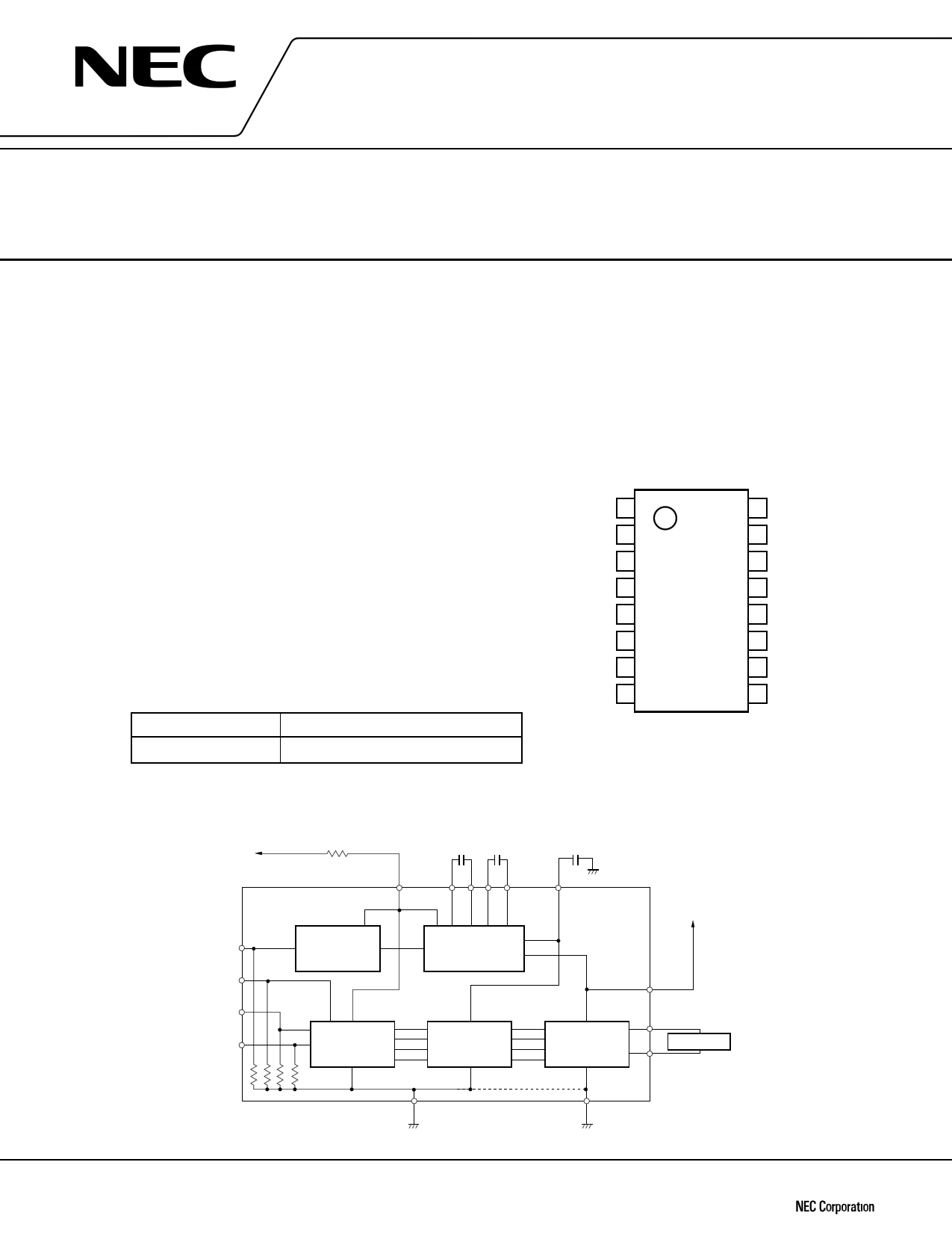
ORDERING INFORMATION
Part Number
µPD16804GS
Package
16-pin plastic SOP (300 mil)
PIN CONFIGURATION (Top View)
C2L 1
C1H 2
C1L 3
VM 4
VDD 5
IN1 6
IN2 7
INC 8
16 C2H
15 VG
14 STBY
13 OUT2
12 PGND
11 OUT1
10 VM
9 DGND
BLOCK DIAGRAM
R1: 50 Ω (external resistor)
VDD
C1 C2
C3
VG
C1 = C2 = C3: External capacitors (10 nF)
STBY
INC
IN1
IN2
Contorol
circuit
Charge pump
circuit
Contorol
circuit
50 kΩ
DGND
Level shift
circuit
D MOS FET
H bridge circuit
VM
OUT1
Load motor
OUT2
PGND
The information in this document is subject to change without notice.
Document No. G11031EJ3V0DS00 (3rd edition)
Date Published July 1997 N
Printed in Japan
©
1997
1 page 
DC-DC
convertor
Battery
VM = 0.5 V to 7.5 V
VDD = 3.0 V to 6.0 V
R1 = 50 Ω Note 2
C1 = C2 = C3 = 10 nF
C1 C2
C3
STBY 14
VDD
5
OSC
circuit
2 3 16 1
15
Charge pump circuit
VM
10
CPU
INC 8
IN1 6
IN2 7
Pull-down resistor
50 kΩ TYP.
Control circuit
Level shift
circuit
D MOS FET
H bridge
circuit
9
DGND
12
PGND
4
VM
C4 Note 1
1 to 10 µF
11 OUT1
13
OUT2
M
Film
take-up motor
IN1 L
IN2 L
H
H
Forward Brake
mode
mode
Reverse
mode
Stop mode
Notes 1. It is recommended to connect a capacitor of 1 to
10 µF between VM and GND to protect the gate of
the DMOS FET from surge voltage.
2. Insert a resistor of 50 (±10) Ω to prevent malfunc-
tioning.
5 Page 
[MEMO]
µPD16804
11
11 Page | ||
| Páginas | Total 12 Páginas | |
| PDF Descargar | [ Datasheet UPD16804GS.PDF ] | |
Hoja de datos destacado
| Número de pieza | Descripción | Fabricantes |
| UPD16804GS | MONOLITHIC H BRIDGE DRIVER CIRCUIT | NEC |
| Número de pieza | Descripción | Fabricantes |
| SLA6805M | High Voltage 3 phase Motor Driver IC. |
Sanken |
| SDC1742 | 12- and 14-Bit Hybrid Synchro / Resolver-to-Digital Converters. |
Analog Devices |
|
DataSheet.es es una pagina web que funciona como un repositorio de manuales o hoja de datos de muchos de los productos más populares, |
| DataSheet.es | 2020 | Privacy Policy | Contacto | Buscar |