|
|
|
PDF RF3322PCBA Data sheet ( Hoja de datos )
| Número de pieza | RF3322PCBA | |
| Descripción | CABLE REVERSE PATH PROGRAMMABLE GAIN AMPLIFIER | |
| Fabricantes | RF Micro Devices | |
| Logotipo | ||
Hay una vista previa y un enlace de descarga de RF3322PCBA (archivo pdf) en la parte inferior de esta página. Total 14 Páginas | ||
|
No Preview Available !
Preliminary
3
Typical Applications
• Euro-DOCSIS/DOCSIS Cable Modems
• CATV Set-Top Boxes
• Telephony Over Cable
RF3322
CABLE REVERSE PATH
PROGRAMMABLE GAIN AMPLIFIER
• Home Networks
• Automotive/Mobile Multimedia
• Coaxial and Twisted Pair Line Driver
3
Product Description
The RF3322 is a variable gain amplifier for use in CATV
reverse path (upstream) applications. It is DOCSIS-com-
pliant for use in cable modems. The gain control covers a
58dB range and is serially programmable via three-wire
digital bus for compatibility with standard baseband
chipsets. Amplifier shutdown and transmit disable modes
are software- and hardware-controlled. The device is
placed into sleep mode via the serial control bus. The
device operates over the frequency band of 5MHz to
65MHz for use in current U.S. and European systems.
The amplifier delivers up to 60dBmV at the output of the
balun. Gain is controllable in accurate 1dB steps. The
device is provided in an industry-standard QSOP-20
package.
Optimum Technology Matching® Applied
Si BJT
üSi Bi-CMOS
GaAs HBT
SiGe HBT
GaAs MESFET
Si CMOS
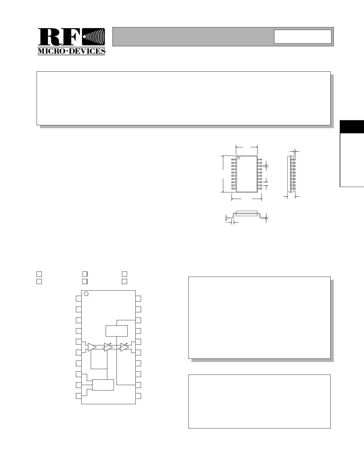
GND 1
VCC1 2
GND 3
GND1 4
VIN+ 5
VIN- 6
GND 7
CS 8
SDA 9
SCLK 10
Power
Control
Gain Control
and Serial Bus
20 GND2
19 VCC2
18 TXEN
17 NC
16 VOUT+
15 VOUT-
14 RAMP
13 NC
12 SHDN
11 GND
0.157
0.150
0.0098
0.0040
0.340
0.333
0.0098
0.0040
0.025
0.244
0.228
0.0688
0.0532
Dimensions in inches.
8° MAX
0° MIN
0.050
0.016
0.010
0.006
NOTES:
1. Shaded lead is Pin 1.
2. All dimensions are excluding mold flash and protrusions.
3. Lead coplanarity: 0 to 0.004 max.
4. Deviation from package center and leadframe center: 0.004 max.
5. Misalignment from top and bottom package centers: 0.004 max.
6. End flash not to exceed 0.006 per side.
Package Style: QSOP-20
Features
• Single 5V Supply
• Differential Input and Output
• -30dB to +28dB Voltage Gain Range
• 5MHz to 65MHz Operation
• Sophisticated Power Management
• DOCSIS 1.1 RF Compliant
Ordering Information
RF3322
Cable Reverse Path Programmable Gain Amplifier
RF3322 PCBA Fully Assembled Evaluation Board
Functional Block Diagram
RF Micro Devices, Inc.
7625 Thorndike Road
Greensboro, NC 27409, USA
Tel (336) 664 1233
Fax (336) 664 0454
http://www.rfmd.com
Rev A2 010518
3-27
1 page 
Preliminary
Table 1. Serial Interface Control Word Format
Bit Mnemonic
Description
MSB 7
6
5
4
3
2
1
LSB 0
D7 Sleep Mode (Software Shutdown)
D6 Test Bit
D5 Gain Control, Bit 5
D4 Gain Control, Bit 4
D3 Gain Control, Bit 3
D2 Gain Control, Bit 2
D1 Gain Control, Bit 1
D0 Gain Control, Bit LSB
Serial Bus Timing Diagram
TES
TDATAH,TDATAL
TDS TDH
TWH
TC
RF3322
3
TEH
D7 D6
D5 D4 D3 D2 D1 D0
Table 2. Timing Data
Parameter
SCLK Pulsewidth
SCLK Period
Setup Time, SDA versus S CLK
Setup Time, CS versus S CLK
Hold Time, SDA versus S CLK
Hold Time, CS versus S CLK
SCLK Pulsewidth, High
SCLK Pulsewidth, Low
Table 3. Programming State
Enter Sleep Mode
Exit Sleep Mode
Enter Shutdown
Exit Shutdown
TX Enable
TX Disable
Rev A2 010518
Symbol
TWH
TC
TDS
TES
TDH
TEH
TDATAH
TDATAL
Min
50
100
10
10
20
20
50
50
Typ
Max
Units
ns
ns
ns
ns
ns
ns
ns
ns
TX SHDND MSB6
XHL
H=High Voltage Logic
X H H*
L=Low Voltage Logic
XLX
X=Don’t Care
X H H* *Gain Control Data Must be Re-Sent
HXX
LXX
3-31
5 Page 
Preliminary
Shutdown Enable
Shutdown enable can be set to be “continuous on”
(chip enabled) by placing the SHDN jumper in the
right-hand position and placing the associated GND/
VCC jumper in the “VCC” position. Shutdown enable
can be set to “continuous off” (chip disabled) by placing
the associated GND/VCC jumper in the “GND” posi-
tion. If a computer controlled signal is used (J1), place
the SHDN jumper in the left-hand position.
SHDN
GND
SHDN
GND
SHDN
GND
VCC
Continuous ON
A
VCC
Continuous OFF
B
VCC
Software Controlled
C
Figure 2. SHDN Enable Configuration
VCC Settings
VCC1 should be set to 5.0VDC.
Evaluation Board Setup
Equipment Needed
• Signal Generator
• Spectrum Analyzer
• Power Supply (5.0V@300mA)
• RF3322 PCBA
• Serial Cable (included with kit)
• Standard PC
• Three-Wire Bus Software
Optional Equipment
• Variable Low-Pass or Band-Pass Filters
• Power Meter
• Second Signal Generator with Modulation for ACPR
and IP2, IP3 Testing
• Arbitrary Wave Generator
• Two-Channel Oscilloscope
Software Setup
To install the software, you need a computer with the
following.
• 133MHz Pentium processor
• 16MB RAM
• Hard Drive with 5MB free space
• Free 25-pin LPT port
• VGA Monitor
The software may be downloaded from www.rfmd.com
by following these steps.
Select the “Product Support” tab;
Select “Evaluation Board Information”;
Select “RF3322”.
RF3322
Unzip the file using WinZip 7.0 or higher (http://
www.winzip.com). Unzip to a temporary directory and
run RF3322.exe.
The 7-bit Gain Control Word (GCW) in the data latch
determines the gain setting in the RF3322. The gain
control data (SDA) load sequence is initiated by a fall-
ing edge on CS. The SDA is serially loaded (MSB first)
into the 7-bit shift register at each rising edge of the
clock. While CS is low, the data latch holds the previ-
ous data word allowing the gain level to remain
unchanged. After seven clock cycles the new data
word is fully loaded and CS is switched high. This
enables the data latch and the loaded register data is
passed to the gain control block with the updated gain
value. Also at this CS transition, the internal clock is
disabled, thus inhibiting new serial input data.
Software and Cable
Figure 3 shows the cable configuration. Connect the
cable into the LPT1 port of the computer running the
software. Connect the other end of the cable to the 25-
pin connector of the evaluation board. Executing the
software (RF3322.exe) will produce the screen shown
in Figure 4. The user may set the gain of the evaluation
board by sliding the gain control switch to the desired
gain setting. Pressing the Preset Gain Value buttons
automatically sets the gain of the unit to the value
shown on the button. The Automatic Gain Adjustment
when set to “Cycle” will automatically cycle through all
of the gain steps (0-58) in seconds (at the rate set by
the user). The user may place the unit in sleep, shut-
down and transmit enable/disable modes by checking
the corresponding box. The bit pattern being sent to
the PCBA is shown at the bottom of the screen. See
README_3322.txt file for proper pin/signal mapping
for the 25 pin interface.
3
Rev A2 010518
3-37
11 Page | ||
| Páginas | Total 14 Páginas | |
| PDF Descargar | [ Datasheet RF3322PCBA.PDF ] | |
Hoja de datos destacado
| Número de pieza | Descripción | Fabricantes |
| RF3322PCBA | CABLE REVERSE PATH PROGRAMMABLE GAIN AMPLIFIER | RF Micro Devices |
| Número de pieza | Descripción | Fabricantes |
| SLA6805M | High Voltage 3 phase Motor Driver IC. |
Sanken |
| SDC1742 | 12- and 14-Bit Hybrid Synchro / Resolver-to-Digital Converters. |
Analog Devices |
|
DataSheet.es es una pagina web que funciona como un repositorio de manuales o hoja de datos de muchos de los productos más populares, |
| DataSheet.es | 2020 | Privacy Policy | Contacto | Buscar |