|
|
|
PDF RF2948B Data sheet ( Hoja de datos )
| Número de pieza | RF2948B | |
| Descripción | 2.4GHz SPREAD-SPECTRUM TRANSCEIVER | |
| Fabricantes | RF Micro Devices | |
| Logotipo | ||
Hay una vista previa y un enlace de descarga de RF2948B (archivo pdf) en la parte inferior de esta página. Total 18 Páginas | ||
|
No Preview Available !
0
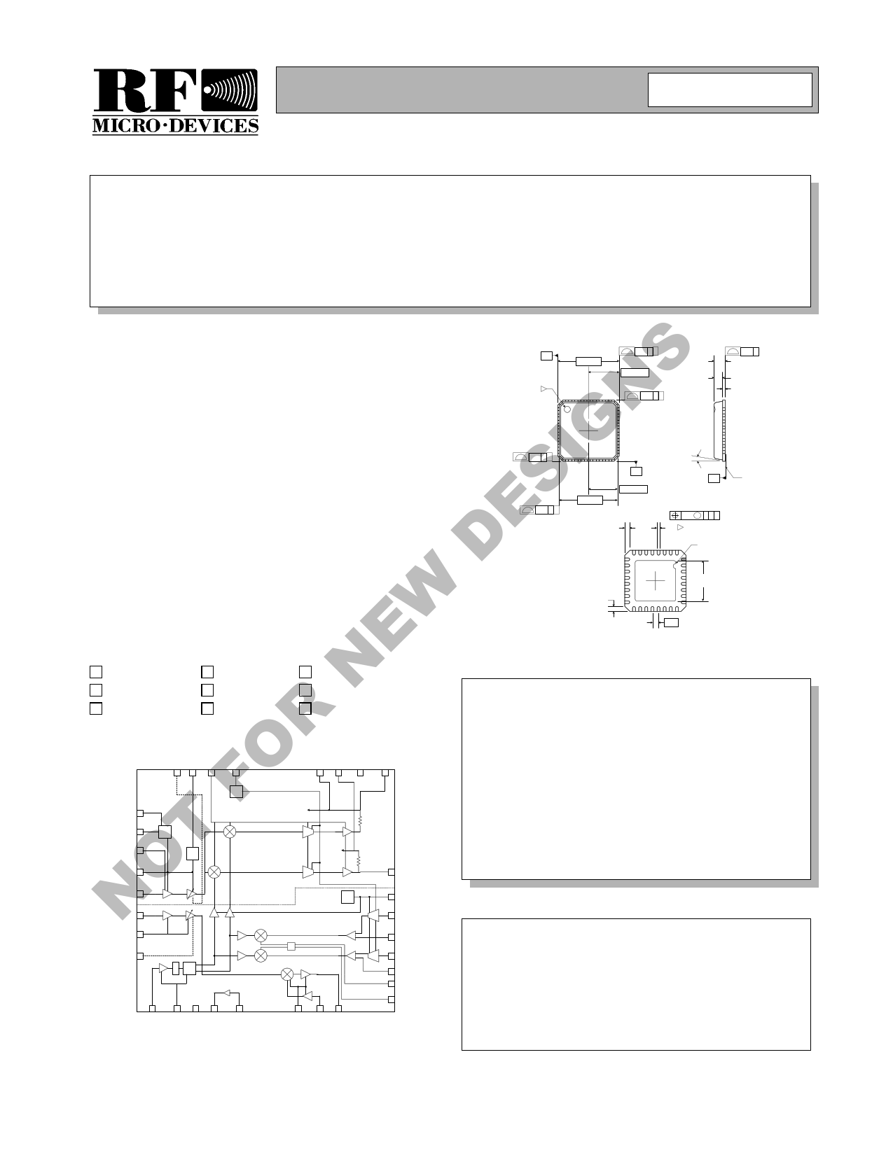
Typical Applications
• IEEE 802.11b WLANs
• Wireless Residential Gateways
• Secure Communication Links
RF2948B
2.4GHz SPREAD-SPECTRUM TRANSCEIVER
• High Speed Digital Links
• Wireless Security
• Digital Cordless Telephones
Product Description
The RF2948B is a monolithic integrated circuit specifi-
cally designed for direct-sequence spread-spectrum sys-
tems operating in the 2.4GHz ISM band. The part
includes: a direct conversion from IF receiver with vari-
able gain control; quadrature demodulator; I/Q baseband
amplifiers; and, on-chip programmable baseband filters.
For the transmit side, a QPSK modulator and upconverter
are provided. The design reuses the IF SAW filter for
transmit and receive reducing the number of SAW filters
required. Two-cell or regulated three-cell (3.6V maxi-
mum) battery applications are supported by the part. The
part is also designed to be part of a 2.4GHz chipset con-
sisting of the RF2494 LNA/Mixer, one of the many RFMD
high-efficiency GaAs HBT PA’s and the RF3000 Base-
band Processor.
2 PLCS
-A-
5.00 SQ.
0.10 C A
2.50 TYP.
3 2 PLCS
0.10 C B
0.05 C
0.90
0.85
0.70
0.65
0.05
0.00
2 PLCS
0.10 C B
-B-
2 PLCS
0.10 C A
4.75 SQ.
2.37 TYP.
Shaded lead is pin 1.
0.60
0.24
TYP.
Dimensions in mm.
0.50
0.30
12°
MAX
-C-
0.10 M C A B
0.30 2
0.18
Pin 1 ID
R.20
3.45
3.15
SQ.
0.50
SEATING
PLANE
Optimum Technology Matching® Applied
Si BJT
9Si Bi-CMOS
GaAs HBT
SiGe HBT
GaAs MESFET
Si CMOS
InGaP/HBT
GaN HEMT
SiGe Bi-CMOS
PD 1
RX EN 2
RX IF BIAS 3
VCC1 4
RX IF IN 5
TX IF IN 6
VCC9 7
TX VGC 8
32 31
30
29
BW
Control
Logic
REF
÷2
Phase
Splitter
9
10 11 12
13
28 27
26
25
DC
Feedback
gm-C
LPF
DC
Feedback
gm-C
LPF
TX
Bias
Σ
14 15 16
24 I OUT
23 VCC4
gm-C
LPF
22 TXQ DATA
21 TXQ BP
gm-C
LPF
20 TXI DATA
19 TXI BP
18 IF1 OUT+
17 IF1 OUT-
Functional Block Diagram
Package Style: QFN, 32-Pin, 5x5
Features
• 45MHz to 500MHz IF Quad Demod
• On-Chip Variable Baseband Filters
• Quadrature Modulator and Upconverter
• 2.7V to 3.6V Operation
• Part of IEEE802.11b Chipset
• 2.4GHz PA Driver
Ordering Information
RF2948B
2.4GHz Spread-Spectrum Transceiver
RF2948BTR13 2.4GHz Spread-Spectrum Transceiver (Tape & Reel)
RF2948B PCBA Fully Assembled Evaluation Board
RF Micro Devices, Inc.
7628 Thorndike Road
Greensboro, NC 27409, USA
Tel (336) 664 1233
Fax (336) 664 0454
http://www.rfmd.com
Rev A6 040930
NOT FOR NEW DESIGNS
11-239
1 page 
RF2948B
Pin
1
2
3
4
5
6
7
8
9
Function
PD
Description
This pin is used to power up or down the transmit and receive base-
band sections. A logic high powers up the quad demod mixers, TX and
RX GmC LPF’s, baseband VGA amps, data amps, and IF LO buffer
amp/ phase splitter. A logic low powers down the entire IC for sleep
mode. Also, see State Decode Table.
Interface Schematic
VCC
Pins
3, 4, 5
10 kΩ
ESD
To
Logic
RX EN
RX IF BIAS
VCC1
RX IF IN
TX IF IN
VCC9
TX VGC
IF LO
Enable pin for the receiver 15dB gain IF amp and the RX VGA amp.
Powers up all receiver functions when PD is high, turns off the receiver
IF circuits when low. Also, see State Decode Table.
When this pin is a logic “high”, the device is in receive mode. When this
pin is a logic “low”, the device is in transmit mode.
Shunt resistor of 23.7±1% to ground. Biases IF AMPS.
See pin 1.
Power supply for RX VGA amplifier, IC logic and RX references.
IF input for receiver section. Must have DC-blocking cap. The capacitor
value should be appropriate for the IF frequency. For half-duplex opera-
tion, connect RX IF IN and TX IF IN signals together after the DC block-
ing caps, then run a transmission line from the output of the IF SAW.
AC coupling capacitor must be less than 150pF to prevent delay in
switching RX to TX/TX to RX.
Input for the TX IF signal after SAW filter. External DC-blocking cap
required. For half-duplex operation, connect RX IF IN and TX IF IN sig-
nals together after the DC-blocking caps, then run a transmission line
from the output of the IF SAW. AC coupling capacitor must be less than
150pF to prevent delay in switching RX to TX/TX to RX.
See pin 6.
IF
SAW
Filter
50 Ω µstrip
DC
Block Pin 7
Pin 8
Power supply for the TX 15dB gain amp and TX VGA.
Gain control setting for the transmit VGA. Positive slope.
IF LO input. Must have DC-blocking cap. The capacitor value should be
appropriate for the IF frequency. LO frequency=2xIF. Quad
mod/demod phase accuracy requires low harmonic content from IF LO,
so it is recommended to use an n=3 LPF between the IF VCO and IF
LO. This is a high impedance input and the recommended matching
approach is to simply add a 100Ω shunt resistor at this input to con-
strain the mismatch.
Recommended Matching
Network for IF LO
IF VCO
C2
150 pF
100 Ω
IF LO
Pin 9
10
VCC8
Power supply for IF LO buffer and quadrature phase network.
11
VCC6
Power supply for transmitter bias generator.
12 PA OUT This is the output transistor of the power amp stage. It is an open col-
lector output. The output match is formed by an inductor to VCC, which
supplies DC and a series cap.
VCC
CBYP
22 nF
L
C
Power
Amp
Output
PA OUT
From
TX RF
Image Filter
PA IN
14 mA
Bias
Rev A6 040930
11-243
5 Page 
TRANSMITTER
TX LPF and Mixers
The transmit section starts with a pair of 5-pole Bessel
filters identical to the filters in the receive section and
with the same 3dB frequency. These filters pre-shape
and band-limit the digital or analog input signals prior
to the first upconversion to IF. These filters have a high
input impedance and expect an input signal of
100mVPP typical. Following these low pass filters are
the I/Q quadrature upconverter mixers. Each of these
mixers is half the size and half the current of the RF to
IF downconverter on the RF2494. Recall that this
upconverted signal may drive the same SAW filter (in
half-duplex mode) as the RF2494 and therefore share
the same load. Having the sum of the two BB to IF mix-
ers equal in size and DC current to the RF to IF mixer,
will minimize the time required to switch between RX
and TX, and will facilitate the best impedance match to
the filter.
TX VGA
Being essentially high impedance, TX IF IN responds
to the input voltage (rather than power), and amplifies
that voltage by the gain specified in the datasheet, then
presents the output voltage at a 50Ω impedance (after
upconversion). For characterization purposes, a 50Ω
shunt resistor is placed on the IF signal path, before
AC-coupling to the input. A 50Ω signal source is
applied directly across the shunt resistor, through a
coaxial test lead. The signal source sees the shunt
resistor and therefore a low SWR. Voltage gain is then
the same as power gain, simply the difference in dB
between the output power and the input power.
The AGC after the SAW filter starts with a switch and a
constant gain amplifier of 15dB, which is identical to
the circuitry on the receive IF AGC. This was done so
that the input impedance will remain constant for differ-
ent gain control voltages. Following this 15dB gain
amplifier is a single stage of gain control offering 15dB
gain range. The main purpose of adding this variable
gain is to give the system the flexibility to use different
SAW filters and image filters with different insertion
loss values. This gain could also be adjusted real time,
if desired.
RF2948B
TX Upconverter
The IF to RF upconverter is a double-balanced differ-
ential mixer with a differential to single-ended con-
verter on the output to supply 0dBm peak linear power
to the image filter. The upconverted SSB signal should
have -6dBm power at this point, and the image will
have the same power, but due to the correlated nature
of the signal and image, the output must support 0dBm
of linear power to maintain linearly.
+6dBm PA Driver
The SSB output of the upconverter is -6dBm of linear
power. The image filter should have at most 4dB of
insertion loss while removing the image, LO, 2LO and
any other spurs. The filter output should supply the PA
driver input -10dBm of power.
The PA driver is a one-stage class A amplifier with
10dB gain and capable of delivering 6dBm of linear
power to a 50Ω load, and has a 1dB compression
point of 12dBm. For lower power applications, this PA
driver can be used to drive a 50Ω antenna directly.
Rev A6 040930
11-249
11 Page | ||
| Páginas | Total 18 Páginas | |
| PDF Descargar | [ Datasheet RF2948B.PDF ] | |
Hoja de datos destacado
| Número de pieza | Descripción | Fabricantes |
| RF2948B | 2.4GHz SPREAD-SPECTRUM TRANSCEIVER | RF Micro Devices |
| RF2948BPCBA | 2.4GHz SPREAD-SPECTRUM TRANSCEIVER | RF Micro Devices |
| RF2948BTR13 | 2.4GHz SPREAD-SPECTRUM TRANSCEIVER | RF Micro Devices |
| Número de pieza | Descripción | Fabricantes |
| SLA6805M | High Voltage 3 phase Motor Driver IC. |
Sanken |
| SDC1742 | 12- and 14-Bit Hybrid Synchro / Resolver-to-Digital Converters. |
Analog Devices |
|
DataSheet.es es una pagina web que funciona como un repositorio de manuales o hoja de datos de muchos de los productos más populares, |
| DataSheet.es | 2020 | Privacy Policy | Contacto | Buscar |