|
|
|
PDF RF2492 Data sheet ( Hoja de datos )
| Número de pieza | RF2492 | |
| Descripción | DUAL-BAND LOW NOISE AMPLIFIER/MIXER | |
| Fabricantes | RF Micro Devices | |
| Logotipo | ||
Hay una vista previa y un enlace de descarga de RF2492 (archivo pdf) en la parte inferior de esta página. Total 22 Páginas | ||
|
No Preview Available !
Preliminary
8
RF2492
DUAL-BAND LOW NOISE AMPLIFIER/MIXER
Typical Applications
• TDMA-GSM Cellular/PCS Handsets
• TDMA Cellular/PCS Handsets
• GAIT Handsets
• CDMA Cellular/PCS Handsets
• GSM DCS/PCS Handsets
Product Description
The RF2492 is a fully featured dual-band LNA/Mixer and
is usable in a variety of mobile handset applications. The
unique dual IF outputs provide interface to two indepen-
dent IF SAW filters supporting applications such as
TDMA-EDGE where 30kHz and 200kHz bandwidth SAW
filters are used. With independent power management
control pins for the LNAs and mixers, either IF output can
be accessed from either high- or low-band LNAs, provid-
ing maximum flexibility with minimum power usage. Multi-
ple gain control options are provided to achieve a very
large dynamic range for the receiver. A frequency doubler
is included in the LO circuit to generate both high- and
low-band LO signals with a single VCO. The RF2492 is
packaged in a 32 pin, 5mmx5mm, leadless plastic pack-
age.
Optimum Technology Matching® Applied
Si BJT
Si Bi-CMOS
GaAs HBT
üSiGe HBT
GaAs MESFET
Si CMOS
25 23
PCS LNA IN 30
LNA GAIN SEL 12
MIX GAIN SEL 14
CELL LNA IN 11
IF SEL 9
LNA IP SEL 10
LNA ISET 17
BAND SEL 31
LOGIC
CONTROL
X2 ENABLE 32
15 18
4 IF1+
5 IF1-
7 IF2-
8 IF2+
X2
1
19 PCS LO OUT+
20 PCS LO OUT -
21 CELL LO OUT+
22 CELL LO OUT-
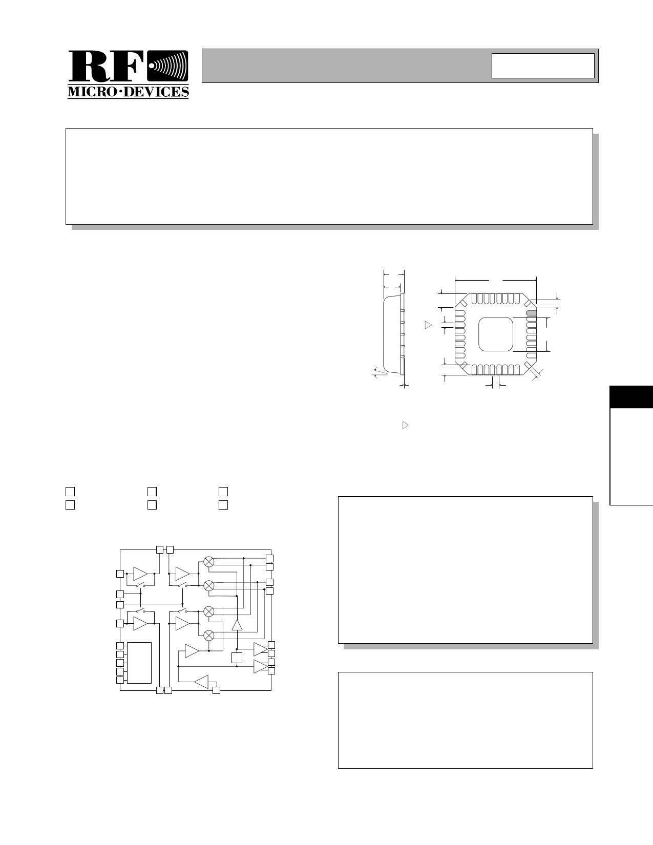
1.00
0.85
0.80
0.65
0.60
0.24 typ
3
0.30
0.18
5.00
sq.
0.45
0.20
4 PLCS
3.25
2.95 sq.
12°
MAX
0.05
0.01
0.55
0.30
0.50
0.23
0.13
4 PLCS
NOTES:
1 Shaded Pin is Lead 1.
2 Pin 1 identifier must exist on top surface of package by identification
mark or feature on the package body. Exact shape and size is optional.
3 Dimension applies to plated terminal: to be measured between 0.02 mm
and 0.25 mm from terminal end.
4 Package Warpage: 0.05 mm max.
5 Die Thickness Allowable: 0.305 mm max.
Package Style: LCC, 32-Pin, 5x5
Features
• Complete Dual-Band Receiver Front End
• Low Noise Figure
• Stepped LNA/Mixer Gain Control
• Adjustable LNA Bias Current/IIP3
• Integrated LO Frequency Doubler
• Differential LO Buffer Outputs
Ordering Information
RF2492
Dual-Band Low Noise Amplifier/Mixer
RF2492 PCBA Fully Assembled Evaluation Board
Functional Block Diagram
RF Micro Devices, Inc.
7625 Thorndike Road
Greensboro, NC 27409, USA
Tel (336) 664 1233
Fax (336) 664 0454
http://www.rfmd.com
8
Rev A4 010828
8-33
1 page 
Preliminary
RF2492
State Table (Typical Values for VCC =2.75V and 3dB RF Filter Insertion Loss)
Cellular
PCS
Parameter
LNA On
LNA at Max IIP3 LNA at Nom IIP3
LNA Off
LNA On
LNA at Max IIP3 LNA at Nom IIP3
LNA Off
Mixer Mixer Mixer Mixer Mixer Mixer Mixer Mixer Mixer Mixer Mixer Mixer
Amp On Amp Off Amp On Amp Off Amp On Amp Off Amp On Amp Off Amp On Amp Off Amp On Amp Off
Cascade
Gain (dB)
24.5 15.9 24 15.4 2 -6.8 24.3 15.3 23.5 14.5 4
-5
Noise Figure (dB)
2.8 5.3 2.7 5.4 18.2 25.2 2.6 5.7 3.1 6.3 17 24
Input IP3 (dBm)
-6.5 +1.1 -6.4
0 +14.9 +19.5 -6
+3 -5.6 +1.5 +14 +21.7
Total Current
38
36
32 26 40
38.5
34.5
28
LNA
Gain (dB)
14.5 14.5
14
14 -7.5 -7.5 14.8 14.8 14
14 -5.5 -5.5
Noise Figure (dB)
2.0 2.0 1.8 1.8 5.8 5.8 1.5 1.5 1.8 1.8 6.2 6.2
Input IP3 (dBm)
+7.5 +7.5
+3
+3 +21 +21 +9
+9 +3.5 +3.5 25
25
Isolation (dB)
LNA Current (mA)
Mixer
Gain (dB)
13 4.4 13 4.4 13 4.4 12.5 3.5 12.5 3.5 12.5 3.5
Noise Figure (dB)
7 14 7 14 7 14 8.5 15.5 8.5 15.5 8.5 15.5
Input IP3 (dBm)
+5.1 +13.8 +5.1 +13.8 +5.1 +13.8 +6 +16 +6 +16 +6 +16
LO Input Level (dBm)
-5
-5
-5
-5
-5
-5
-5
-5
-5
-5
-5
-5
LO to RF Isolation(dB)
Mixer Current (mA)
8
Control Logic Table
PCS IF2 High Gain/High
Linearity
PCS IF2 High Gain/Nomi-
nal Linearity
PCS IF2 Mid1 Gain
PCS IF2 Mid2 Gain
PCS IF2 Low Gain
Cell IF2 High Gain/
High Linearity
Cell IF2 High Gain/Nomi-
nal Linearity
Cell IF2 Mid1 Gain
Cell IF2 Mid2 Gain
Cell IF2 Low Gain
Cell IF1 High Gain/
High Linearity
Cell IF1 High Gain/
Nominal Linearity
Cell IF1 Mid1 Gain
Cell IF1 Mid2 Gain
Cell IF1 Low Gain
Shutdown
Not Defined
BAND SEL
1
1
1
1
1
0
0
0
0
0
0
0
0
0
0
X
1
IF SEL
0
0
0
0
0
0
0
0
0
0
1
1
1
1
1
X
1
LNA GAIN
1
1
1
0
0
1
1
1
0
0
1
1
1
0
0
X
X
MIX GAIN LNA IP SEL
11
10
00
10
00
11
10
00
10
00
11
10
00
10
00
XX
XX
ENABLE
1
1
1
1
1
1
1
1
1
1
1
1
1
1
1
0
1
Rev A4 010828
8-37
5 Page 
Preliminary
RF2492
Evaluation Board Layout
Board Size 3.0” x 3.0”
Board Thickness 0.0616”, Board Material FR-4, Multi-Layer
Assembly
8
Rev A4 010828
8-43
11 Page | ||
| Páginas | Total 22 Páginas | |
| PDF Descargar | [ Datasheet RF2492.PDF ] | |
Hoja de datos destacado
| Número de pieza | Descripción | Fabricantes |
| RF2492 | DUAL-BAND LOW NOISE AMPLIFIER/MIXER | RF Micro Devices |
| RF2494 | HIGH FREQUENCY LNA/MIXER | RF Micro Devices |
| RF2495 | LOW CURRENT LNA/MIXER | RF Micro Devices |
| RF2498 | TRI-BAND/QUAD-MODE CDMA/GPS LOW NOISE AMPLIFIER/MIXER | RF Micro Devices |
| Número de pieza | Descripción | Fabricantes |
| SLA6805M | High Voltage 3 phase Motor Driver IC. |
Sanken |
| SDC1742 | 12- and 14-Bit Hybrid Synchro / Resolver-to-Digital Converters. |
Analog Devices |
|
DataSheet.es es una pagina web que funciona como un repositorio de manuales o hoja de datos de muchos de los productos más populares, |
| DataSheet.es | 2020 | Privacy Policy | Contacto | Buscar |