|
|
|
PDF TISP3072F3 Data sheet ( Hoja de datos )
| Número de pieza | TISP3072F3 | |
| Descripción | DUAL SYMMETRICAL TRANSIENT VOLTAGE SUPPRESSORS | |
| Fabricantes | Power Innovations Limited | |
| Logotipo | ||
Hay una vista previa y un enlace de descarga de TISP3072F3 (archivo pdf) en la parte inferior de esta página. Total 16 Páginas | ||
|
No Preview Available !
Copyright © 1997, Power Innovations Limited, UK
TISP3072F3, TISP3082F3
DUAL SYMMETRICAL TRANSIENT
VOLTAGE SUPPRESSORS
MARCH 1994 - REVISED SEPTEMBER 1997
TELECOMMUNICATION SYSTEM SECONDARY PROTECTION
q Ion-Implanted Breakdown Region
Precise and Stable Voltage
Low Voltage Overshoot under Surge
DEVICE
‘3072F3
‘3082F3
VDRM
V
58
66
V(BO)
V
72
82
q Planar Passivated Junctions
Low Off-State Current < 10 µA
q Rated for International Surge Wave Shapes
WAVE SHAPE
2/10 µs
8/20 µs
10/160 µs
10/560 µs
0.5/700 µs
10/700 µs
10/1000 µs
STANDARD
FCC Part 68
ANSI C62.41
FCC Part 68
FCC Part 68
RLM 88
FTZ R12
VDE 0433
CCITT IX K17/K20
REA PE-60
ITSP
A
80
70
60
45
38
50
50
50
35
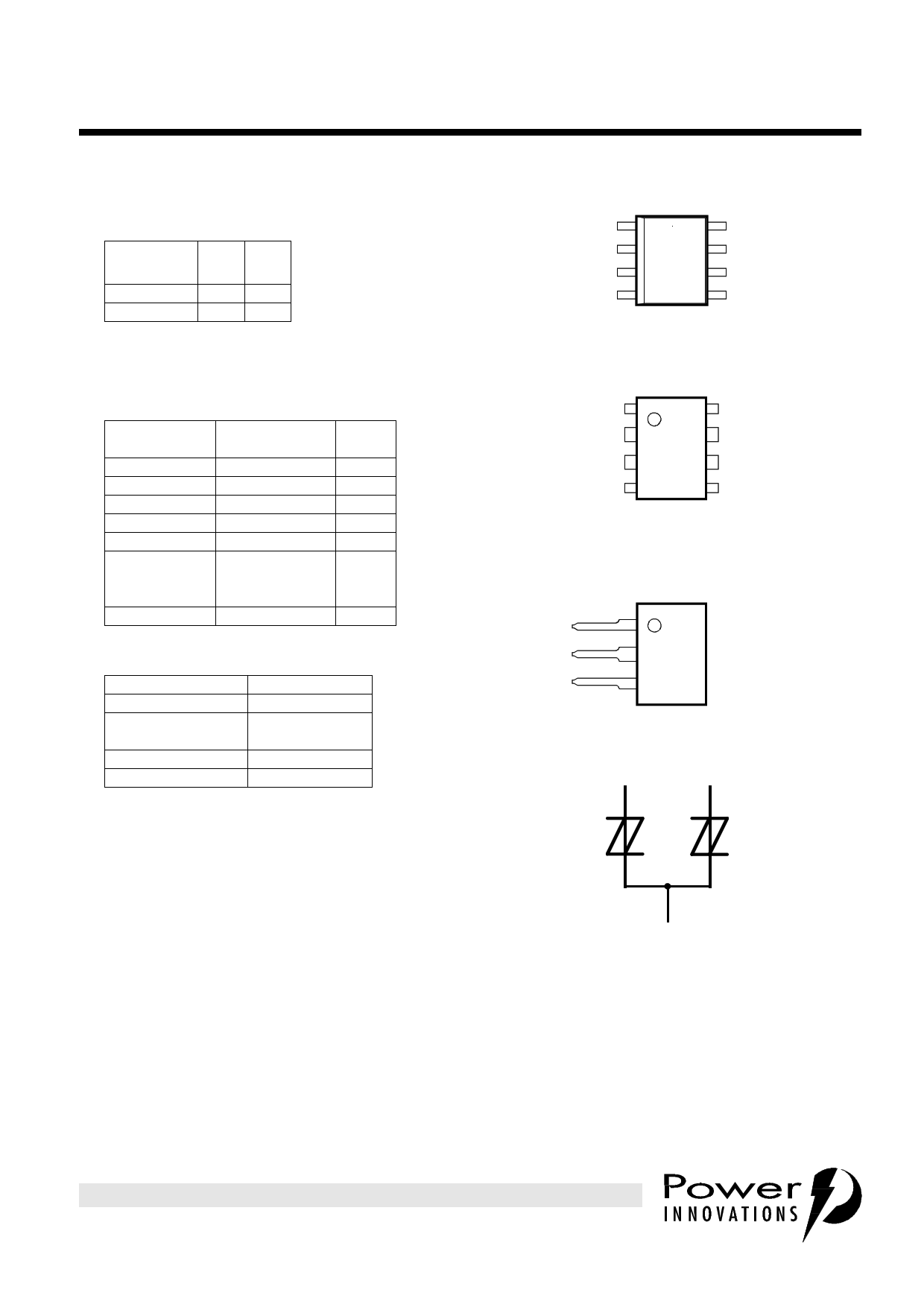
q Surface Mount and Through-Hole Options
D PACKAGE
(TOP VIEW)
T1
NC 2
NC 3
R4
8G
7G
6G
5 G MDXXAE
NC - No internal connection
P PACKAGE
(TOP VIEW)
T1
8T
G2
7G
G3
R4
6G
5R
MDXXAF
Specified T terminal ratings require connection of pins 1 and 8.
Specified R terminal ratings require connection of pins 4 and 5.
SL PACKAGE
(TOP VIEW)
T1
G2
PACKAGE
Small-outline
Small-outline taped
and reeled
Plastic DIP
Single-in-line
PART # SUFFIX
D
DR
P
SL
R3
device symbol
T
MDXXAG MD23AA
R
q UL Recognized, E132482
description
These low voltage dual symmetrical transient
voltage suppressor devices are designed to
protect ISDN applications against transients
caused by lightning strikes and a.c. power lines.
Offered in two voltage variants to meet battery
and protection requirements they are guaranteed
to suppress and withstand the listed international
lightning surges in both polarities. Transients are
initially clipped by breakdown clamping until the
voltage rises to the breakover level, which
causes the device to crowbar. The high crowbar
holding current prevents d.c. latchup as the
current subsides.
SD3XAA
G
Terminals T, R and G correspond to the
alternative line designators of A, B and C
These monolithic protection devices are
fabricated in ion-implanted planar structures to
ensure precise and matched breakover control
and are virtually transparent to the system in
normal operation
PRODUCT INFORMATION
Information is current as of publication date. Products conform to specifications in accordance
with the terms of Power Innovations standard warranty. Production processing does not
necessarily include testing of all parameters.
1
1 page 
TISP3072F3, TISP3082F3
DUAL SYMMETRICAL TRANSIENT
VOLTAGE SUPPRESSORS
MARCH 1994 - REVISED SEPTEMBER 1997
TYPICAL CHARACTERISTICS
T and G, or R and G terminals
NORMALISED BREAKDOWN VOLTAGES
vs
JUNCTION TEMPERATURE
TC3LAJ
Normalised to V(BR)
1.2 I(BR) = 100 µA and 25°C
Negative Polarity
100
ON-STATE CURRENT
vs
ON-STATE VOLTAGE
TC3LAL
1.1
V(BR)M
10
1.0 V(BO)
V(BR)
150°C
25°C
-40°C
0.9
-25 0 25 50 75 100 125 150
1
1
2 3 4 5 6 7 8 9 10
TJ - Junction Temperature - °C
Figure 4.
VT - On-State Voltage - V
Figure 5.
HOLDING CURRENT & BREAKOVER CURRENT
vs
JUNCTION TEMPERATURE
TC3LAH
1.0
0.9
0.8
0.7
0.6
0.5
I(BO)
0.4
0.3
IH
0.2
0.1
-25
0 25 50 75 100 125
TJ - Junction Temperature - °C
Figure 6.
150
PRODUCT INFORMATION
5
5 Page 
TISP3072F3, TISP3082F3
DUAL SYMMETRICAL TRANSIENT
VOLTAGE SUPPRESSORS
MARCH 1994 - REVISED SEPTEMBER 1997
APPLICATIONS INFORMATION
longitudinal balance
Figure 18 shows a three terminal TISP with its equivalent "delta" capacitance Each capacitance, CTG , CRG
and CTR , is the true terminal pair capacitance measured with a three terminal or guarded capacitance
bridge. If wire R is biased at a larger potential than wire T then CTG > CRG . Capacitance CTG is equivalent to
a capacitance of CRG in parallel with the capacitive difference of (CTG - CRG ). The line capacitive unbalance
is due to (CTG - CRG ) and the capacitance shunting the line is CTR + CRG/2 .
Figure 18.
All capacitance measurements in this data sheet are three terminal guarded to allow the designer to
accurately assess capacitive unbalance effects. Simple two terminal capacitance meters (unguarded third
terminal) give false readings as the shunt capacitance via the third terminal is included.
PRODUCT INFORMATION
11
11 Page | ||
| Páginas | Total 16 Páginas | |
| PDF Descargar | [ Datasheet TISP3072F3.PDF ] | |
Hoja de datos destacado
| Número de pieza | Descripción | Fabricantes |
| TISP3072F3 | DUAL SYMMETRICAL TRANSIENT VOLTAGE SUPPRESSORS | Power Innovations Limited |
| Número de pieza | Descripción | Fabricantes |
| SLA6805M | High Voltage 3 phase Motor Driver IC. |
Sanken |
| SDC1742 | 12- and 14-Bit Hybrid Synchro / Resolver-to-Digital Converters. |
Analog Devices |
|
DataSheet.es es una pagina web que funciona como un repositorio de manuales o hoja de datos de muchos de los productos más populares, |
| DataSheet.es | 2020 | Privacy Policy | Contacto | Buscar |