|
|
|
PDF U2405B Data sheet ( Hoja de datos )
| Número de pieza | U2405B | |
| Descripción | Fast Charge Controller for Drained NiCd/NiMH Batteries | |
| Fabricantes | TEMIC Semiconductors | |
| Logotipo | ||
Hay una vista previa y un enlace de descarga de U2405B (archivo pdf) en la parte inferior de esta página. Total 17 Páginas | ||
|
No Preview Available !
U2405B
Fast Charge Controller for Drained NiCd/NiMH Batteries
Description
The fast-charge battery controller circuit, U2405B, uses
bipolar technology. The IC enables the designer to create
an efficient and economic charge system. The U2405B
incorporates intelligent multiple-gradient battery-
voltage monitoring and mains phase control for power
management. With automatic top-off charging, the
Features
D Preformation algorithm for drained batteries
D Multiple gradient monitoring
D Temperature window (Tmin/Tmax)
D Exact battery voltage measurement without charge
D Phase control for charge-current regulation
D Top-off and trickle charge function
D Two LED outputs for charge status indication
D Disabling of d2V/dt2 switch-off criteria
during battery formation
D Battery-voltage check
18 (20) 17 (19) 16 (18)
14 (15)
integrated circuit ensures that the charge device stops
regular charging before the critical stage of overcharging
is achieved. It incorporates an additional algorithm for
reactivating fully drained batteries especially after long-
time storage. It has two LED driver indications for charge
and temperature status.
Applications
D Portable power tools
D Laptop/notebook personal computer
D Cellular/cordless phones
D Emergency lighting systems
D Hobby equipment
D Camcorder
Package: DIP18, SO20
13 (14)
12 (13) 11 (12)
4 (4)
1 (1)
Sync
ö
C
ö
R
Phase control
Vöi
Trigger output
Power - on control
VRef
6.5 V/10 mA
Oscillator
Control unit
Gradient
d2V/dt2 and –dV
15 (17)
2 (2)
Power supply
VS = 8 to 26 V
160 mV
Ref
Temp. control
Tmax Sensor
94 8585
5 (5) 6 (6)
7 (8) 8 (9)
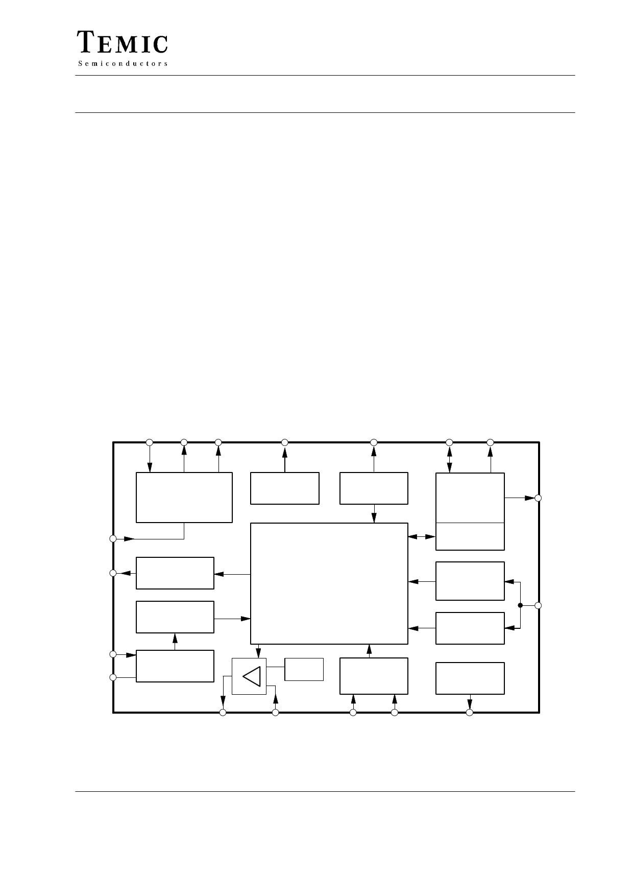
Figure 1. Block diagram
Status control
Scan path
Battery
detection
VRef = 5 V
VBatt Monitor
0.1 to 4 V
3 (3)
10 (11)
Charge break
output
9 (10)
( ) SO 20, Pins 7 and 16 NC
TELEFUNKEN Semiconductors
Rev. A2, 14-Nov-96
1 (17)
1 page 
U2405B
Flow Chart Explanation, fosc = 800 Hz
(Figures 2, 3 and 4)
Battery pack insertion disables the voltage lock at battery
detection input Pin 10. All functions in the integrated
circuit are reset. For further description, DIP-pinning is
taken into consideration.
Battery Insertion and –DV
Monitoring
After battery insertion fast charge Io begins when the
input voltage VBatt is higher than 1.6 V. For the first
5 minutes the d2V/dt2-gradient recognition is suppressed,
–DV monitoring is activated. In case the detected VBatt
voltage is less then 1.6 V, the special preformation
procedure will be activated. The reference level with
respect to the cell voltage can be adjusted by the resistor
RB3 (see figure 2).
Preformation Procedure
Before fast charge of fully drained or long time stored
batteries begin, a reactivation is necessary. The
preformation current is dependent on pull-up resistor
RB1. The fast charge starts only after the VBatt is higher
than 1.6 V level. During the first 10 minutes the green
LED2 is blinking. If, after 10 minutes, VBatt voltage has
not reached the reference level, the indication changes to
red blinking LED1. The charge will continue with
preformation rate I (RB1). In case VBatt increases to 1.6 V
reference level, the fast charge rate current, Io, is
switched-on and the green LED2 is blinking.
–DV Cut-Off (Monitoring)
When the signal at Pin 10 of the DA converter is 12 mV
below the actual value, the comparator identifies it as a
voltage drop of –DV. The validity of –DV cut-off is
considered only if the actual value is below 12 mV for
three consecutive cycles of measurement.
d2V/dt2-Gradient
If there is no charge stop within the first 5 minutes after
battery insertion, then d2V/dt2 monitoring will be active.
In this actual charge stage, all stop-charge criteria are
active.
When close to the battery’s capacity limit, the battery
voltage curve will typically rise. As long as the +d2V/dt2
stop-charging criteria are met, the device will stop the fast
charge activities.
Top-Off Charge Stage
By charge disconnection through the + d2V/dt2 mode, the
device switches automatically to a defined protective
top-off charge with a pulse rate of 1/4 IO (pulse time,
tp = 5.12 s, period, T = 20.48 s).
The top-off charge time is specified for a time of
20 minutes @ 800 Hz.
Trickle Charge Stage
When top-off charge is terminated, the device switches
automatically to trickle charge with 1/256 IO (tp = 5.12 s,
period = 1310.72 s). The trickle continues until the
battery pack is removed.
Basic Description
Power Supply, Figure 2
The charge controller allows the direct power supply of
8 to 26 V at Pin 15. Internal regulation limits higher input
voltages. Series resistance, R1, regulates the supply
current, IS, to a maximum value of 25 mA. Series
resistance is recommended to suppress the noise signal,
even below 26 V limitation. It is calculated as follows.
wR1min
Vmax–26 V
25 mA
vR1max
Vmin– 8 V
Itot
where
Itot = IS + IRB1 + I1
Vmax, Vmin = Rectified voltage
IS = Current consumption (IC) without load
IRB1 = Current through resistance, RB1
I1 = Trigger current at Pin 1
TELEFUNKEN Semiconductors
Rev. A2, 14-Nov-96
5 (17)
5 Page 
U2405B
Status Control
Status control inside and outside the charging process are designated by LED1 and LED2 outputs given in the table
below:
LED1 (red)
OFF
OFF
ON
Blinking
ON
OFF
LED2 (green)
Status
ON Top-off charge, trickle charge
Blinking Quick charge
OFF Temperature out of the window
OFF Drained battery (0.1 V < VBatt > 1.6 V, if t > 10 min.)
Battery break, short circuit
Blinking Temperature out of window before battery insertion or power on
OFF No battery (VBatt > 5 V)
The blink frequency of LED outputs can be calculated as
+follows:
f(LED)
Oscillator frequency, fosc
1024
Oscillator
Time sequences regarding measured values and
evaluation are determined by the system oscillator. All
the technical data given in the description are with the
standard frequency 800 Hz.
It is possibe to alter the frequency range in a certain
limitation. Figure 9 shows the frequency versus
resistance curves with different capacitance values.
Oscillation Frequency Adjustment
Recommendations:
0.5C charge
0.5 500 Hz =
250 Hz
1C charge
2C charge
500 Hz
2 500 Hz = 1000 Hz
3C charge
3 500 Hz = 1500 Hz
10000
1000
CO=2.2nF
CO=10nF
100
CO=4.7nF
10
0.1
95 11408
1
fO ( kHz )
Figure 9. Frequency versus resistance for different capacitance values
TELEFUNKEN Semiconductors
Rev. A2, 14-Nov-96
10
11 (17)
11 Page | ||
| Páginas | Total 17 Páginas | |
| PDF Descargar | [ Datasheet U2405B.PDF ] | |
Hoja de datos destacado
| Número de pieza | Descripción | Fabricantes |
| U2405B | Fast Charge Controller for Drained NiCd/NiMH Batteries | TEMIC Semiconductors |
| Número de pieza | Descripción | Fabricantes |
| SLA6805M | High Voltage 3 phase Motor Driver IC. |
Sanken |
| SDC1742 | 12- and 14-Bit Hybrid Synchro / Resolver-to-Digital Converters. |
Analog Devices |
|
DataSheet.es es una pagina web que funciona como un repositorio de manuales o hoja de datos de muchos de los productos más populares, |
| DataSheet.es | 2020 | Privacy Policy | Contacto | Buscar |