|
|
|
PDF V58C265404S Data sheet ( Hoja de datos )
| Número de pieza | V58C265404S | |
| Descripción | HIGH PERFORMANCE 2.5 VOLT 16M X 4 DDR SDRAM 4 BANKS X 4Mbit X 4 | |
| Fabricantes | Mosel Vitelic Corp | |
| Logotipo | ||
Hay una vista previa y un enlace de descarga de V58C265404S (archivo pdf) en la parte inferior de esta página. Total 30 Páginas | ||
|
No Preview Available !
MOSEL VITELIC
V58C265404S
HIGH PERFORMANCE
2.5 VOLT 16M X 4 DDR SDRAM
4 BANKS X 4Mbit X 4
PRELIMINARY
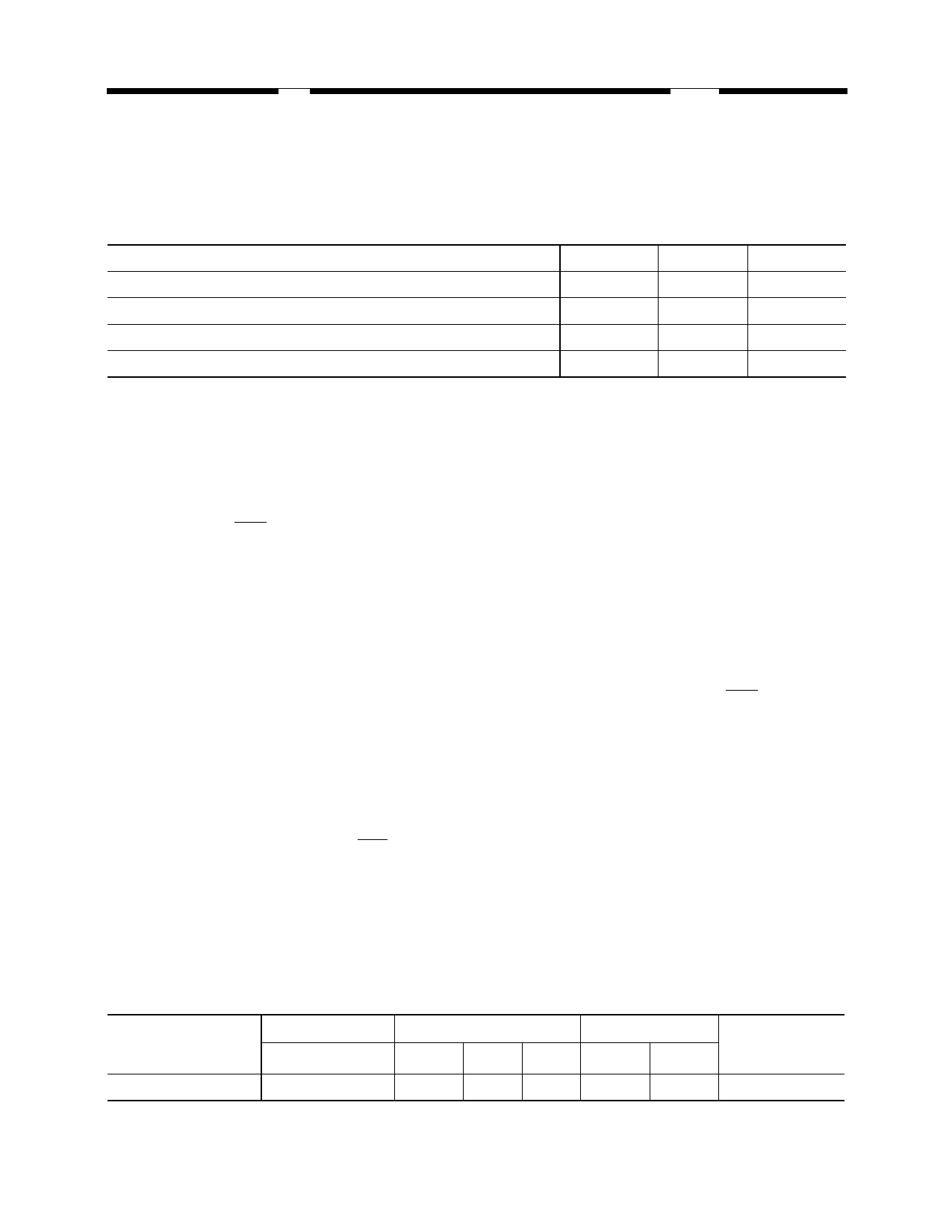
System Frequency (fCK)
Clock Cycle Time (tCK3)
Clock Cycle Time (tCK2.5)
Clock Cycle Time (tCK2)
6
166 MHz
6 ns
6.5 ns
7ns
7
143 MHz
7 ns
7.5 ns
8ns
8
125 MHz
8 ns
9 ns
10ns
Features
s 4 banks x 4Mbit x 4 organization
s High speed data transfer rates with system
frequency up to 166 MHz
s Data Mask for Write Control (DM)
s Four Banks controlled by BA0 & BA1
s Programmable CAS Latency: 2, 2.5, 3
s Programmable Wrap Sequence: Sequential
or Interleave
s Programmable Burst Length:
2, 4, 8 for Sequential Type
2, 4, 8 for Interleave Type
s Automatic and Controlled Precharge Command
s Suspend Mode and Power Down Mode
s Auto Refresh and Self Refresh
s Refresh Interval: 4096 cycles/64 ms
s Available in 66-pin 400 mil TSOP-II
s SSTL-2 Compatible I/Os
s Double Data Rate (DDR)
s Bidirectional Data Strobe (DQs) for input and
output data, active on both edges
s On-Chip DLL aligns DQ and DQs transitions with
CLK transitions
s Differential clock inputs CLK and CLK
s Power supply 2.5V ± 0.2V
Description
The V58C265404S is a four bank DDR DRAM or-
ganized as 4 banks x 4Mbit x 4. The V58C265404S
achieves high speed data transfer rates by employ-
ing a chip architecture that prefetches multiple bits
and then synchronizes the output data to a system
clock
All of the control, address, circuits are synchro-
nized with the positive edge of an externally sup-
plied clock. I/O transactions are possible on both
edges of DQS.
Operating the four memory banks in an inter-
leaved fashion allows random access operation to
occur at a higher rate than is possible with standard
DRAMs. A sequential and gapless data rate is pos-
sible depending on burst length, CAS latency and
speed grade of the device.
Device Usage Chart
Operating
Temperature
Range
0°C to 70 °C
Package Outline
JEDEC 66 TSOPII
•
CLK Cycle Time (ns)
–6 -7 -8
• ••
Power
Std.
•
L
•
Temperature
Mark
Blank
V58C265404S Rev. 1.4 January 2000
1
1 page 
MOSEL VITELIC
V58C265404S
Functional Description
s Power-Up Sequence
The following sequence is required for POWER UP.
1. Apply power and attempt to maintain CKE at a low state (all other inputs may be undefined.)
- Apply VDD before or at the same time as VDDQ.
- Apply VDDQ before or at the same time as VTT & Vref.
2. Start clock and maintain stable condition for a minimum of 200us.
3. The minimum of 200us after stable power and clock (CLK, CLK), apply NOP & take CKE high.
4. Precharge all banks.
5. Issue EMRS to enable DLL.(To issue “DLL Enable” command, provide “Low” to A0, “High” to BA0
and “Low” to all of the rest address pins, A1~A11 and BA1)
6. Issue a mode register set command for “DLL reset”. The additional 200 cycles of clock input is
required to lock the DLL. (To issue DLL reset command, provide “High” to A8 and “Low” to BA0)
7. Issue precharge commands for all banks of the device.
8. Issue 2 or more auto-refresh commands.
9. Issue a mode register set command to initialize device operation.
Note1 Every “DLL enable” command resets DLL. Therefore sequence 6 can be skipped during power up. Instead of it,
the additional 200 cycles of clock input is required to lock the DLL after enabling DLL.
Power up Sequence & Auto Refresh(CBR)
CK, CK
Command
01 23 45 678
••
2 Clock min.
2 Clock min.
tRP
EMRS
MRS
DLL Reset
precharge
ALL Banks
1st Auto
Refresh
45 67
9 10 11 12 13 14 15 16 17 18 19
••
tRFC
••
••
2nd Auto
Refresh
min.200 Cycle
••
7
••
tRFC
••
••
••
2 Clock min.
Mode
Register Set
Any
Command
Extended Mode Register Set (EMRS)
The extended mode register stores the data for enabling or disabling DLL. The default value of the extend-
ed mode register is not defined, therefore the extended mode register must be written after power up for en-
abling or disabling DLL. The extended mode register is written by asserting low on CS, RAS, CAS, WE and
high on BA0 (The DDR SDRAM should be in all bank precharge with CKE already high prior to writing into
the extended mode register). The state of address pins A0 ~ A11 and BA1 in the same cycle as CS, RAS,
CAS and WE low is written in the extended mode register. Two clock cycles are required to complete the
write operation in the extended mode register. The mode register contents can be changed using the same
command and clock cycle requirements during operation as long as all banks are in the idle state. A0 is used
for DLL enable or disable. “High” on BA0 is used for EMRS. All the other address pins except A0 and BA0
must be set to low for proper EMRS operation. A1 is used at EMRS to indicate I/O strength A1 = 0 full strength,
A1 = 1 half strength. Refer to the table for specific codes.
V58C265404S Rev. 1.4 January 2000
5
5 Page 
MOSEL VITELIC
V58C265404S
Data Strobe Preamble and Postamble Timings for DDR Read Cycles
(CAS Latency = 2; Burst Length = 2)
T0 T1 T2 T3 T4
CK, CK
Command
DQS
DQ
READ
NOP
tRPRE(min)
NOP
NOP
tRPRE(max)
tRPST(min)
tDQSQ(min)
tRPST(max)
D0 D1
tDQSQ(max)
Consecutive Burst Read Operation and Effects on the Data Strobe Preamble and Postamble
Burst Read Operation (CAS Latency = 2; Burst Length = 4)
CK, CK
Command
DQS
DQ
ReadA
NOP
ReadB
NOP
NOP
NOP
NOP
NOP
D0A D1A D2A D3A D0B D1B D2B D3B
Burst Read Operation (CAS Latency = 2; Burst Length = 4)
CK, CK
Command
DQS
DQ
ReadA
NOP
NOP
ReadB
NOP
NOP
NOP
NOP
D0A D1A D2A D3A
D0B D1B D2B D3B
NOP
NOP
V58C265404S Rev. 1.4 January 2000
11
11 Page | ||
| Páginas | Total 30 Páginas | |
| PDF Descargar | [ Datasheet V58C265404S.PDF ] | |
Hoja de datos destacado
| Número de pieza | Descripción | Fabricantes |
| V58C265404S | HIGH PERFORMANCE 2.5 VOLT 16M X 4 DDR SDRAM 4 BANKS X 4Mbit X 4 | Mosel Vitelic Corp |
| Número de pieza | Descripción | Fabricantes |
| SLA6805M | High Voltage 3 phase Motor Driver IC. |
Sanken |
| SDC1742 | 12- and 14-Bit Hybrid Synchro / Resolver-to-Digital Converters. |
Analog Devices |
|
DataSheet.es es una pagina web que funciona como un repositorio de manuales o hoja de datos de muchos de los productos más populares, |
| DataSheet.es | 2020 | Privacy Policy | Contacto | Buscar |