|
|
|
PDF XC95103SL Data sheet ( Hoja de datos )
| Número de pieza | XC95103SL | |
| Descripción | Synchronous Step-Down DC/DC Converter with Built-In LDO Regulator In Series plus Voltage Detector | |
| Fabricantes | Torex Semiconductor | |
| Logotipo | ||
Hay una vista previa y un enlace de descarga de XC95103SL (archivo pdf) en la parte inferior de esta página. Total 9 Páginas | ||
|
No Preview Available !
XC9510 Series
October 28, 2003 Ver. 4
Synchronous Step-Down DC/DC Converter with Built-In LDO Regulator In Series plus Voltage Detector
Preliminary
! Input Voltage Range
! Output Voltage Range
! Switching Frequency
! Output Current
! Ultra Small Packages
! Ceramic Capacitor Compatible
2.4V ~ 6.0V
DC/DC 0.9 ~ 4.0V (±2%)
VR 0.9 ~ 4.0V (±2%)
VD 0.9 ~ 5.0V (±2%)
300kHz, 600kHz, 1.2MHz
DC/DC 800mA
VR 600mA
SOP-8
! APPLICATIONS
" CD-R / RW, DVD
" HDD
" PDAs, portable communication modem
" Cellular phones
" Palmtop computers
" Cameras, video recorders
! GENERAL DESCRIPTION
The XC9510 series consists of a step-down DC/DC converter and a
high-speed LDO regulator connected in series with the DC/DC
converter's output. A voltage detector is also built-in. A highly
efficient, low noise output is possible since the regulator is stepped-
down further from the DC/DC output.
The DC/DC converter block incorporates a P-Channel driver transistor
and a synchronous N-Channel switching transistor. With an external
coil, diode and two capacitors, the XC9510 can deliver output currents
up to 800mA at efficiencies over 90%. The XC9510 is designed for
use with small ceramic capacitors.
A choice of three switching frequencies are available, 300 kHz, 600
kHz, and 1.2 MHz.
Output voltage settings for the DC/DC and VR are set-up internally in
0.1V steps within the range of 0.9V to 4.0V (± 2.0%). For the VD, the
range is of 0.9V to 5.0V (± 2.0%).
The soft start time of the series is internally set to 5ms. With the built-
in U.V.L.O. (Under Voltage Lock Out) function, the internal P-channel
driver transistor is forced OFF when input voltage becomes 1.4 V or
lower.
The operational states of the DC/DC and the regulator blocks can be
changed by inputting three kinds of voltage level via the CE/MODE pin.
The functions of the MODE pin can be selected via the external control
pin to switch the DC/DC control mode and the disable pin to shut down
the regulator block.
! FEATURES
Input Voltage Range : 2.4V ~ 6.0V
Load Capacitors :
Ceramic Capacitors Compatible
(Low ESR Capacitors)
VD Function :
Detects output voltage from the VDOUT pin
while sensing either VDD, DCOUT,
or VROUT internally.
Nch Open Drain Output
<DC/DC Converter>
Output Voltage Range : 0.9 ~ 4.0V (Accuracy ±2%)
Output Current :
800mA
Controls :
PWM Control
PWM, PWM / PFM Automatic
Switching External
Oscillation Frequency : 300kHz, 600kHz, 1.2MHz
<Regulator>
Output Voltage Range : 0.9 ~ 4.0V (Accuracy ±2%)
Current Limit
600mA
Dropout Voltage :
240mV @ IOUT=300mA (VOUT=2.8V)
High Ripple Rejection 60dB @1kHz (VOUT=2.8V)
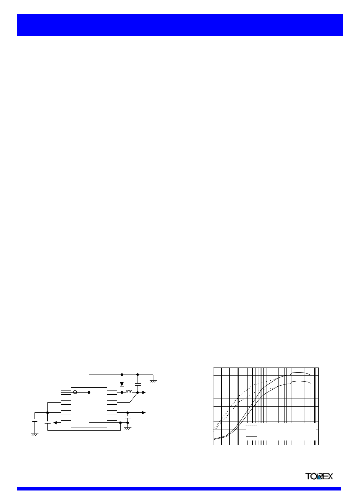
! TYPICAL APPLICATION CIRCUIT
SD
1 LX 8
PGND
2
CE/
MODE
DCOUT
7
L
CL1
DCOUT
3 VDD VROUT 6
CIN
4 VDOUT AGND 5
VROUT
CL2
SOP-8 (Top View)
! TYPICAL PERFORMANCE CHARACTERISTICS
XC9510Hxxxx
DC/DC Efficiency (DCOUT:3.4V, 1.2MHz), VR Efficiency (VROUT:3.0V)
VIN=5.0V, Topr=25OC, L:4.7uH(CDRH4D28C),
CIN:4.7uF(ceramic), CL1:10uF(ceramic), CL2:1uF(ceramic)
100
90
80
70
60
50
40
30
20
10
0
0.1
PWM/PFM switching control
PWM control
1 10 100
DC/DC Output Current IDOUT
VR Output Current IROUT (mA)
1000
Data Sheet
1
Semiconductor Ltd.
1 page 
XC9510 Series
Synchronous Step-Down DC/DC Converter with Built-In LDO Regulator In Series plus Voltage Detector
Preliminary
! ELECTRICAL CHARACTERISTICS (Continued)
$ Detector (2.7V product)
Ta=25OC
PARAMETER
SYMBOL
CONDITIONS
MIN.
TYP.
MAX. UNITS TEST CIRCUIT
Detect Voltage
VDF
2.646
2.700
2.754
V
8
Hysteresis Range
VD Output Current
Output Voltage
Temperature Characteristics
VHYS
IVD
! VDF
! Topr " VDF
VDOUT=0.5V
-40OC<Topr<85OC
3 5 8%-
1 - - mA 9
-
±100
-
ppm
/OC
8
Test Conditions : Unless otherwise stated; * VROUT(T) : Setting Output Voltage
DC/DC : VIN=3.6V [@ DCOUT:2.2V]
VD : VIN=6.0V
VR : VIN = VROUT(T) + 1.0 (V) [When VROUT(T) <1.4V, VIN =2.4V]
note 1 : VD operates when in stand-by mode.
note 2 : Including hysteresis operating voltage range.
note 3 : On resistance = 0.05V / ILX
note 4 : EFFI = { ( Output Voltage x Output Current ) / ( Input Voltage x Input Current) } x 100
note 5 : Time until it short-circuits DCOUT with GND through 1Ω of resistance from a state of operation
and is set to DCOUT=0V from current limit pulse generating.
note 6 : Vdif = (VIN1 (note 7) - VROUT1 (note 8 ) )
note 7 : VIN 1 = The input voltage when VROUT1 appears as input voltage is gradually decreased.
note 8 : VROUT1 = A voltage equal to 98% of the output voltage whenever an amply stabilized IOUT {VROUT(T) + 1.0V} is input.
Data Sheet
5
Semiconductor Ltd.
5 Page | ||
| Páginas | Total 9 Páginas | |
| PDF Descargar | [ Datasheet XC95103SL.PDF ] | |
Hoja de datos destacado
| Número de pieza | Descripción | Fabricantes |
| XC95103SL | Synchronous Step-Down DC/DC Converter with Built-In LDO Regulator In Series plus Voltage Detector | Torex Semiconductor |
| XC95103SR | Synchronous Step-Down DC/DC Converter with Built-In LDO Regulator In Series plus Voltage Detector | Torex Semiconductor |
| Número de pieza | Descripción | Fabricantes |
| SLA6805M | High Voltage 3 phase Motor Driver IC. |
Sanken |
| SDC1742 | 12- and 14-Bit Hybrid Synchro / Resolver-to-Digital Converters. |
Analog Devices |
|
DataSheet.es es una pagina web que funciona como un repositorio de manuales o hoja de datos de muchos de los productos más populares, |
| DataSheet.es | 2020 | Privacy Policy | Contacto | Buscar |