|
|
|
PDF IRFD310 Data sheet ( Hoja de datos )
| Número de pieza | IRFD310 | |
| Descripción | 0.4A/ 400V/ 3.600 Ohm/ N-Channel Power MOSFET | |
| Fabricantes | Intersil Corporation | |
| Logotipo | ||
Hay una vista previa y un enlace de descarga de IRFD310 (archivo pdf) en la parte inferior de esta página. Total 6 Páginas | ||
|
No Preview Available !
Data Sheet
IRFD310
July 1999 File Number 2324.4
0.4A, 400V, 3.600 Ohm, N-Channel
Power MOSFET
These are N-Channel enhancement mode silicon gate
power field effect transistors. They are advanced power
MOSFETs designed, tested, and guaranteed to withstand a
specified level of energy in the breakdown avalanche mode
of operation. All of these power MOSFETs are designed for
applications such as switching regulators, switching
convertors, motor drivers, relay drivers, and drivers for high
power bipolar switching transistors requiring high speed and
low gate drive power. These types can be operated directly
from integrated circuits.
Formerly developmental type TA17444.
Ordering Information
PART NUMBER
PACKAGE
BRAND
IRFD310
HEXDIP
IRFD310
NOTE: When ordering, use the entire part number.
Features
• 0.4A, 400V
• rDS(ON) = 3.600Ω
• Single Pulse Avalanche Energy Rated
• SOA is Power Dissipation Limited
• Nanosecond Switching Speeds
• Linear Transfer Characteristics
• High Input Impedance
• Related Literature
- TB334 “Guidelines for Soldering Surface Mount
Components to PC Boards”
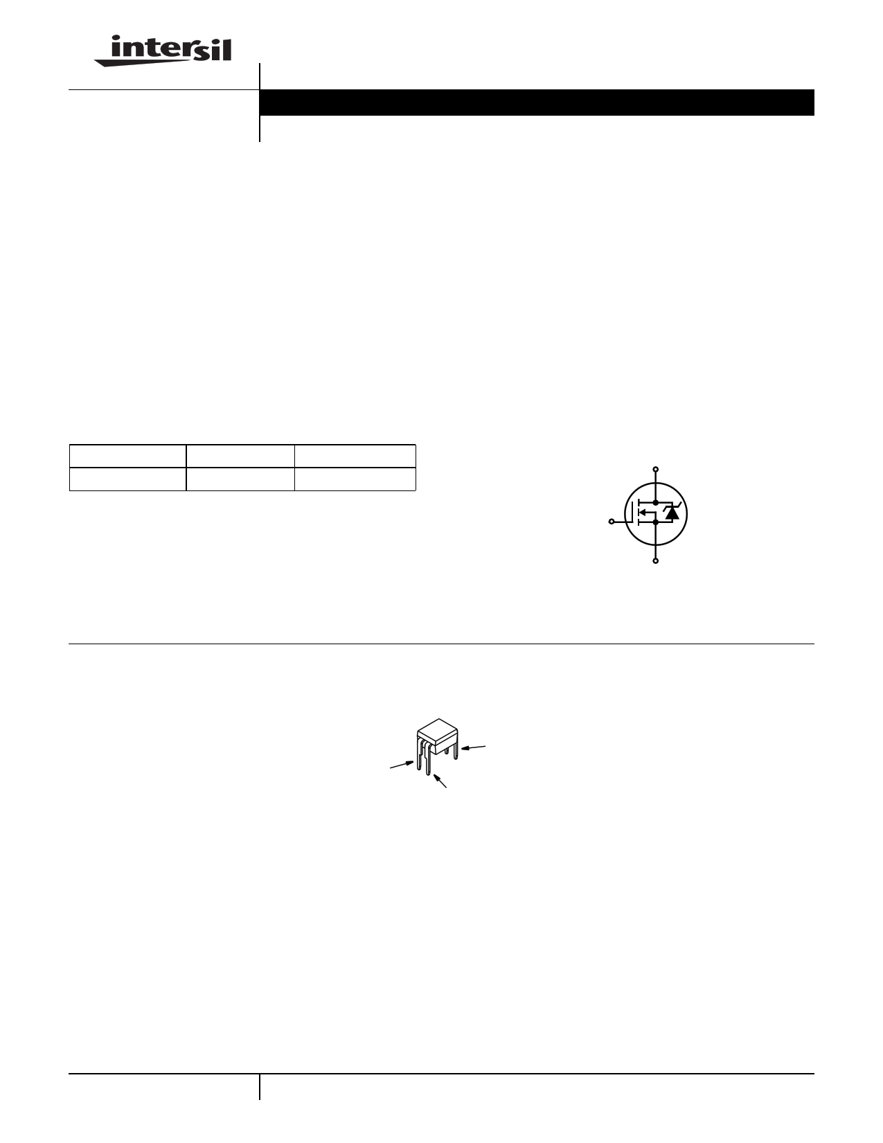
Symbol
D
G
S
Packaging
HEXDIP
GATE
DRAIN
SOURCE
4-293
CAUTION: These devices are sensitive to electrostatic discharge; follow proper ESD Handling Procedures.
http://www.intersil.com or 407-727-9207 | Copyright © Intersil Corporation 1999
1 page 
IRFD310
Typical Performance Curves Unless Otherwise Specified (Continued)
3.0
PULSE DURATION = 80µs
DUTY CYCLE = 0.5% MAX
2.4
1.8
1.2
0.6
TJ = -55oC
TJ = 25oC
TJ = 125oC
0
0
0.44
0.88
1.32
1.76
2.2
I D, DRAIN CURRENT (A)
FIGURE 11. TRANSCONDUCTANCE vs DRAIN CURRENT
10
PULSE DURATION = 80µs
DUTY CYCLE = 0.5% MAX
5.0
2.0
1.0
0.5
TJ = 150oC
0.2 TJ = 25oC
0.1
0
1.0 2.0 3.0 4.0
VSD, SOURCE TO DRAIN VOLTAGE (V)
5.0
FIGURE 12. SOURCE TO DRAIN DIODE VOLTAGE
20
ID = 4A
15
10
VDS = 80V
VDS = 200V
VDS = 320V
5
0
0 2 4 6 8 10
Qg, GATE CHARGE (nC)
FIGURE 13. GATE TO SOURCE VOLTAGE vs GATE CHARGE
Test Circuits and Waveforms
VARY tP TO OBTAIN
REQUIRED PEAK IAS
VGS
tP
0V
RG
VDS
L
DUT
+
VDD
-
IAS
0.01Ω
FIGURE 14. UNCLAMPED ENERGY TEST CIRCUIT
tP
IAS
BVDSS
VDS
VDD
0
tAV
FIGURE 15. UNCLAMPED ENERGY WAVEFORM
4-297
5 Page | ||
| Páginas | Total 6 Páginas | |
| PDF Descargar | [ Datasheet IRFD310.PDF ] | |
Hoja de datos destacado
| Número de pieza | Descripción | Fabricantes |
| IRFD310 | 0.4A/ 400V/ 3.600 Ohm/ N-Channel Power MOSFET | Intersil Corporation |
| IRFD310 | Power MOSFET(Vdss=400V/ Rds(on)=3.6ohm/ Id=0.35A) | International Rectifier |
| Número de pieza | Descripción | Fabricantes |
| SLA6805M | High Voltage 3 phase Motor Driver IC. |
Sanken |
| SDC1742 | 12- and 14-Bit Hybrid Synchro / Resolver-to-Digital Converters. |
Analog Devices |
|
DataSheet.es es una pagina web que funciona como un repositorio de manuales o hoja de datos de muchos de los productos más populares, |
| DataSheet.es | 2020 | Privacy Policy | Contacto | Buscar |